


12
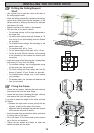
INSTALLING THE COOKER HOOD
Please ensure that when the appliance is installed it is easily accessible to an engineer in the event of a
breakdown.
All installations must comply with the local authorities requirements for the discharge of exhaust air.
Incorrect installation may affect the safety of this cooker hood.
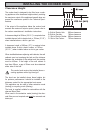
Installation Requirements
Before installation check the wall to which the cooker hood is to be fi tted for electric cables, water pipes or
gas.
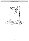
This cooker hood is designed to be fi xed to any horizontal surface over a cooking area, and can be used in the
extraction (ducted to the outside) or recirculation mode.
The installation work must be undertaken by a qualifi ed and competent person.
The manufacturer disclaims any responsibility for damage due to incorrect installation of the cooker hood or if the
hood is not installed in compliance with relevant regulations controlling this type of installation.
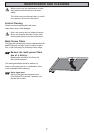
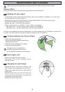
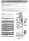
Unpacking
Before unpacking the cooker hood position the carton
with the arrows pointing upwards as illustrated on the
carton.
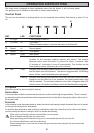
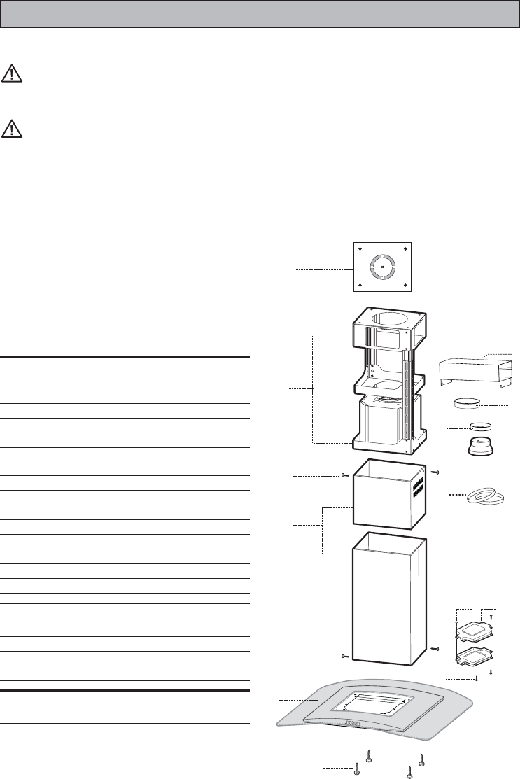
The cooker hood is made up of the following com-
ponents:
Ref. Q.ty Product Components
1 1 Hood Body, complete with: Controls, Light,
Blower, Filters
2 1 Telescopic Chimney comprising:
2.1 1 Upper Section
2.2 1 Lower Section
7.1 1 Telescopic frame complete with extractor,
consisting of:
7.1a 1 Upper frame
7.1b 1 Lower frame
9 1 Reducer Flange ø 150-120 mm
9.1 1 ø120-125 Ducting fl ange
10 1 Flange ø 150
15 1 Air Outlet Connection
24 1 Junction box
25 2 Pipe clamps
Ref. Q.ty Installation Components
12c 6 Screws 2,9 x 9,5
12e 2 Screws 2,9 x 6,5
12f 4 Screws M6 x 10
21 1 Drilling template
Q.ty Documentation
1 Instruction Manual
12c
7.1a
7.1
7.1b
2
2.1
2.2
12c
21
12f
24
12e
15
12c
9
10
1
25
9a