


www.enviromaster.com
Side Discharge Condensers
5
INSTALLATION INSTRUCTIONS
UNIT MOUNTING INSTRUCTIONS
Continued
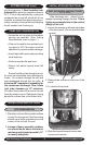
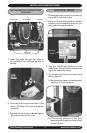
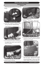
5. Insert lag bolts through the holes in
the bottom of the unit and tighten to
secure.
6. Insert lag bolts through the holes in the
feet on the back of the unit and tighten
to secure.
7. Replace the front panel, do not tighten
the side screws at this time.
Lag Bolts
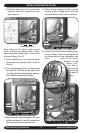
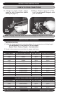
Compressor
Accumulator
Capacitor
Filter Drier
3. Use only HACR type breakers or time
delay fuses. Select the wire size accord-
ing to the ampacity rating.
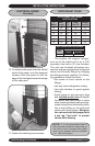
4. To access electrical connections and
wiring diagram:
a) Remove the screws on the side panel
adjacent to the back panel.
Rating
Plate
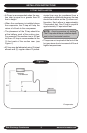
ELECTRICAL WIRING
1. All electrical wiring must be run accord-
ing to NEC and local codes.
2. Refer to the unit rating plate for voltage,
minimum circuit ampacity and over cur-
rent protection requirements.
b) The screws adjacent to the front
panel should already be loose (don't
remove them).
S1C
Shown
S1C
Shown