


www.enviromaster.com
Side Discharge Condensers
7
INSTALLATION INSTRUCTIONS
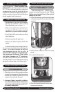
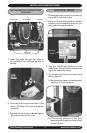
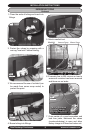
10. To replace side panel slide the slotted
holes of the panel onto the loosened
screws of the front panel so that the
edge of the front panel covers the edge
of the side panel.
ELECTRICAL WIRING
Continued
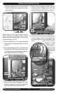
11. Fasten all remaining loose screws.
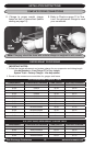
REFRIGERANT PIPING
The system will support refriger-
ant runs to the inside unit of up to 100'
equivalent feet with a 35' rise included.
The units are furnished with sweat con-
nections and are equipped with refrigerant
valves and Schrader ttings for charging
and taking pressure readings. The follow-
ing precautions should be made:
• Be certain no burrs remain on the
ttings.
• Use only clean refrigeration tubing.
• Use tube benders to guard against
kinking.
• Avoid piping on wet and rainy days
and insulate suction line. Be certain
that plastic end caps remain in place
when inserting through wall openings.
Isolate tubing from transmitting vibra-
tion to the building or unit and avoid
contact with sharp edges. Refrigera-
tion valves should be wrapped with
a wet rag "heat sink" to protect
valves while brazing.
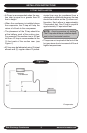
NOTE: It is recommended that a
lter drier be installed in liquid line, at
the indoor unit on models that a lter
drier is not already factory installed
(i.e. 18K and larger).
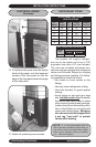
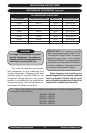
INTERCONNECTING TUBING
SPECIFICATIONS
S1
Model
MAX.
Length
Max.
Lift
Liquid
Line O.D.
Suction
Line O.D.
09 100’ 35’ 1/4" 1/2"
12 100’ 35’ 1/4" 1/2"
18 100’ 35’ 3/8" 5/8"
24 100’ 35’ 3/8" 3/4"
30 100’ 35’ 3/8" 3/4"
36 100’ 35’ 3/8" 3/4"
S2C TUBING SPECIFICATIONS
Circuit
Size
Line Sizes O.D.
Liquid Suction
09, 12 1/4” 1/2”