


www.enviromaster.comSide Discharge Condensers
6
INSTALLATION INSTRUCTIONS
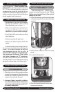
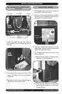
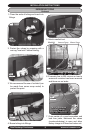
c. Slide the side panel out to access the
high/low electrical connections and
wire diagram.
Note: Remove the plastic edge guards
from the holes and replace with a water-
tight strain relief tting (High V) and a split
grommet tting (low V)
5. Power should be run to a weather proof
disconnect box usually within 3 feet of
the unit.
6. From the disconnect box, run the power
through the 7/8" hole on the side of the
unit and into the electrical box and an-
chor with the strain relief tting.
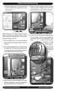
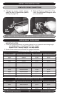
7. Run wires to the high Volt pigtail in the con-
trol box and attach L1 and L2 connections.
Also run green wire to ground wire.
High Volt Connection
Plastic Edge Guards
High Volt
Low Volt
Low Volt Connection
8. Check wiring diagram for the required
number of low voltage wires to be run
between indoor and outdoor sections.
Completed Electrical Connections
S1C
S1C
Shown
S1C
S1C
Shown
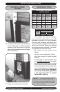
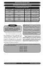
9. Connect the 24 Volt wiring matching color
to color. Refer to the wiring diagram on
the inside panel of the condenser, and
a l so refer to the wiring
diagram on the
indoor unit.
Low Volt in-
terconnect
should be
at least 18
awg.