


9. Service Diagnosis.
The table below is intended as a quick reference to aid the service engineer to determine the cause of a particular malfunction as well as the
recommended repair. It is not intended to be an exclusive list.
Reference to other portions of the manual inclusive of wiring diagrams, installation and operating instructions are recommended to better
determine the cause of a problem.
Symptom Possible cause Correction
Warning RED LED ON See Page 20. See Page 20.
No Warning RED LED ON P.C. Board inoperative Remove board and check.
No power to machine Check electrical source.
Bin Full Amber LED ON Bin Full of Ice. None.
Magnetic Switch inoperative Check and replace.
Machine Runs but compressor not running. P.C. Board compressor relay open. Test and Replace.
Compressor Contactor open. Test and Replace.
Compressor relay open. Test and Replace.
Compressor Winding open. Test and Replace.
Machine runs, makes ice, Ice thickness control open. Check sensor fingers to determine if covered
does not try to harvest. with scale or sediment.
Water Too soft Water electrical conductivity must be higher
than 20 uS.
Machine will not run with demineralized water.
Built in relay on P.C. Board open. Check and replace P.C. Board.
Machine runs makes ice and Low Refrigerant Charge. Check system for correct refrigerant charge.
harvests ice but very slowly. Check system for leak.
Low ice capacity High discharge pressure due to under Reclaim refrigerant and recharge with the
condensing or refrigerant overcharge. correct amount.
Inefficient Compressor. Replace compressor.
Dirty condenser. Clean Condenser.
Low water flow (water cooled only). Check and repair.
High air temperature (Air-cooled only). Check temperature of air entering condenser.
Machine makes irregular ice. Water distributor blocked. Clean water distributor.
Expansion valve superheat wrong. Adjust or replace.
Low refrigerant charge. Check for leak, reclaim refrigerant and
recharge with correct amount.
11
7. Service Specification
In servicing a machine, it is offen useful to compare individual units operating characteristics to those of a normally operating machine. The
data that follows gives those characteristics; however, be aware that these values are for a NEW, CLEAN machine. USE THESE NUMBERS
AS A GUIDELINE ONLY.
COMPONENT R22 - R404A Machines
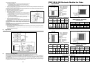
Reservoir level 30-35 mm
Cube Size Control Ice Sensor
distance from evaporator 7mm
High Pressure Safety Switch
Water-cooled C/IN 13 bar - C/OUT 20 bar
Fan Pressure Control
Air-cooled only C/IN 15 bar - C/OUT 13 bar
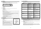
7.1 Operating Characteristics
On air-cooled models during the freezing cycle the discharge pressure is maintained between 13 and 15 bar by means of fan pressure
control and at the same time, the suction pressure will also decline reaching its lowestpoint just before harvest. Compressor amps experience
a similar drop.
On water-cooled models the discharge pressure is constantly maintained during the freeze cycle by the water regulating valve at 13 bar.
However, suction pressure and compressor amps, will still decline as the machine freezes ice.
7.2 Freeze Cycle
R22 Machines R404A Machines
Suction Pressure at the beginning of the Freeze Cycle 2.8/2.5 bar 3.5 bar
Average Discharge Pressure A/C 14 bar 15.5 bar
Average Discharge Pressure W/C 13 bar 17 bar
Suction Pressure at the end of the Freeze Cycle 1.5/1.3 bar 1.7 bar
Freeze Time 20/25 Minutes 20/25 Minutes
Amps. drawn at the beginning of the Freeze Cycle FMIC 180 5.5 5.0
Freeze Cycle FMIC 260 Beginning 7.6 8.0
Amps. drawn at the end of the Freeze Cycle FMIC 180 4.4 4.0
Freeze Cycle FMIC 260 End 4.6 5.5
Suction Pressure at the end of the Freeze Cycle 1.5 1.7
7.3 Harvest Cycle
R22 Machines R404A Machines
Average Discharge Pressure 9 bar 13/15 bar
Average Suction Pressure 7.5 bar 7.5 bar
The values listed are representative of values seen at a wide range of air and water temperatures and are for a normal cube size. When
comparing these figures to field data, allow a variation from each end of the range given.
Refrigerant charge R22 Machines R404A Machines
Model FMIC180 FMIC260 FMIC180 FMIC260
Air cooled l000gr l500gr 1200gr 1700gr
Water cooled 650gr 700gr 1200gr 900gr
Refrigerant metering device
Expansion valve
NOTE: Always check nameplate on individual ice machine for special refrigerant charge before charging the refrigeration system.
Such refrigerant charge is the average charge for the Modular Cubers. However, it is important to check nameplate for each
machine.
8. Component Description
8.1 Toggle Switch - ICE/OFF/WASH
Is a double pole-double throw switch. In OFF position keeps the electric circuit open through the P.C. Board built-in ON-OFF switch. In ICE
position the unit electric circuit is closed for normal operation of electric component.
In WASH position opens the electric circuit to the compressor contactor and fan motors and closes the circuit for the water pump.
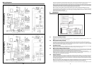
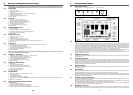
8.2 Electronic Control Board
Located in the control box, this board is the brain of the system as it governs the ice machine cyclematic through sensors, relays and
switches. The sensor is the ice thickness control which signals to the P.C. Board to energise the built-in relay that controls the Hot Gas Valve
and Water Drain Valve. The other contactor to which the P.C. Board supply power is on the compressor line.
The switches are: the Toggle ICE/OFF/WASH switch and the N.C. microswitch/magnetic switch actuated by the evaporator deflector that
signals to the P.C. Board that ice has been defrosted and released, so that the relay controlling the defrost can be disconnected.
The P.C. Board is equipped with an electronic safety timer that turns-on automatically the unit to defrost cycle when the freezing cycle is
longer than 40 minutes and trips-off the complete unit when defrost cycle is longer then 4 minutes.
18
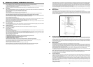
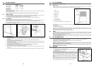
At this point, the unit initiates the defrost cycle. The hot gas circulating into the evaporator serpentine causes a slight melting of the ice cubes
which get released from their moulds. Once entirely released the ice cubes drop simultaneously into the ice storage bin below; in doing so
they move apart from the evaporator bottom end of the plastic deflector. This plastic deflector has on its upper left corner a metal actuator
which, on account of the deflector’s swinging motion, caused by the ice dropping in the bin, pushes the microswitch plunger to open and
close the N.C. contacts. This will, in turn, de-activate the relay contacts that control the hot gas and water drain valve which get de-energised
allowing the unit to start a new freezing cycle. On later models the sequence is controlled by a magnetic switch attached to the bottom right
hand side of the deflector.
When the ice bin is full of ice, the last batch of ice cubes released from the evaporator accumulates to keep the bottom end of the plastic
deflector in open position; with the N.C. microswitch/magnetic switch contact open for longer than 30sec the entire unit stops.