


10. Maintenance, Cleaning and Sanitation Instructions.
The Foster Modular Ice Cuber represents a sizeable investment of time and money in any company’s business.
In order to receive the best return for the investment periodic maintenance is essential.
It is the USER’S RESPONSIBILITY to see that the machine is maintained and the following is a list of recommended instruction to keep the
machine running with a minimum of problems.
Maintenance and Cleaning should be scheduled at the minimum twice per year while sanitation at least once per month.
10.1 Icemaker
THE FOLLOWING MAINTENANCE SHOULD BE SCHEDULED FOR AT LEAST TWO TIMES PER YEAR ON THE ICE MAKER AND
SHOULD BE CARRIED OUT BY YOUR AUTHORISED SERVICE AGENT.
Check and clean or service any optional water treatment devices, if installed.
Clean water strainer.
Check that the cabinet is level, checking from front to back and side to side.
Clean/ Sanitise the water system, evaporator plate and water reservoir using a solution of Citric Acid. (refer to Cleaning Icemaker).
Note: Cleaning/ Sanitising requirements vary according to local water conditions and individual user operation.
Continuous checks of the clarity of the ice cubes and visual inspection of the water systems parts, evaporator plate and the
reservoir before and after cleaning will indicate frequency and procedure to be followed.
Check and tighten all bolts and screws.
Check for water leaks and secure as necessary.
Check the bin control to test shut off. Holding the evaporator deflector in the open position for more than 30 seconds should cause the ice
machine to hut off. Once the deflector has been returned to the closed position the ice making process will restart.
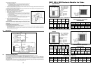
Check cube size, make adjustments to the ice thickness sensor as necessary.
Switch the machine OFF clean the condenser using a vacuum cleaner, brush between the fins using a soft brush. DO NOT USE A WIRE
BRUSH. Instruct the user to clean condenser frequently.
10.2 Ice Storage Bin
The interior of the ice storage bin is in contact with food products, ICE, and should be cleaned and sanitised regularly. Once a week sanitise
it with a commercial food grade sanitiser in compliance with the manufacturer instruction.
10.3 Cabinet Exterior.
Wipe clean the machine and ice bin exterior with a clean cloth or tissue soaked in a mild solution of soapy water.
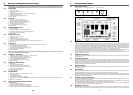
10.4 Cleaning Ice Maker
Empty the bin of ice.
Remove the front panel.
Wait till the end of the defrost/harvest cycle then push and hold the RESET BUTTON for 6 to 8 seconds. The machine will stop with the
blinking of the Amber LED (slow blink)
Pour 100gr of citric acid directly into the reservoir then push the RESET BUTTON again for a short while. The water pump starts to operate
with the fast blinking of the Amber LED, the water inlet valve will be energised till the reservoir is full.
After 15 minutes push the RESET BUTTON for a short while. The P.C.Board will put the machine in automatic rinsing mode with the Amber
LED blinking (blinking twice and then repeat).
NOTE: Rinsing mode consists of:
(a) Energising the water drain valve and the water pump for 40 seconds to empty the reservoir.
(b) De-energise the water drain valve and the water pump for 1 minute.
(c) Energise the water inlet valve till the reservoir is full.
(d) Energise the water pump for 1 minutes.
The above sequence is repeated 7 time so as to be sure that all traces of citric acid have been removed.
At the end of the 7th rinsing cycle the P.C>Board stops the operation of the machine and the Amber LED will be blinking slowly.
Push and hold the reset button for 6 to 8 seconds the machine will restart in the freezing mode.
Replace the evaporator deflector and front panel.
Check the next batch of ice to be sure all of the cleaner has gone (no sour taste).
Caution- DO NOT use ice cubes produced from the cleaning solution. Ensure none remain in the storage bin.
Pour hot water into the storage bin to melt any cubes that may remain and to also clean the bin drain.
12
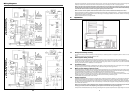
6.3 Refrigeration System During Harvest
The refrigeration system performs the harvest of ice by use of a hot gas bypass valve. When the time comes to de-ice the evaporators, the
hot gas valve is energised, and the high temperature, high pressure gas bypasses the condenser, and is allowed directly into the evaporator.
The high pressure gas is cooled by the cold evaporator so it condenses into a liquid, giving up its heat as it does so. This heat warms the
evaporator and the ice frozen onto the evaporator surface melts, releasing the frozen cubes. Ice then falls by gravity into the storage bin.
The liquid refrigerant goes through the suction line into the heat exchanger where it boils-off so that only refrigerant vapour is drawn into the
suction tube of the compressor.
6.4 Water System
During the harvest cycle, the electric water drain valve is energised thereby opening the drain line.
All water remaining in the reservoir at the end of freezing cycle is pumped-out, to the waste, through the water solenoid and drain line during
the entire defrost cycle eliminating any possible build-up and accumulation of minerals concentration and impurities in the water reservoir.
As the pump stops, the incoming water, passing through the float valve, has still sufficient time, before beginning the next freezing cycle, to
properly fill up the sump/reservoir, so that there would not be any cavitation problem when the water pump resumes its operation, granting
thereby a beffer ice formation inside the cooling cells.
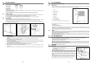
When the released ice cubes drop into the bin, they open-up for a fraction of a second the bottom end of the plastic deflector.
The deflectors swinging motion is enough to reset the contact of the N.C. microswitch/magnetic switch which - via electronic control board
- de-energises the water drain valve allowing the unit to initiate a new freezing cycle.
NOTE: If the interface P.C. Board does not receive the pulse from the second microswitch/magnetic switch, after 30-32 seconds
from the first pulse it will send the signal to the main Board, to switch the unit from defrost to freezing cycle.
The harvest cycle lasts about 1 1/2 to 2 minutes.
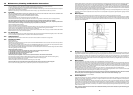
6.5 Control Sequence
At the start of the freezing cycle, the N.C. contacts of the microswitch/magnetic switch mechanically operated by the actuator plate of the
deflector cover are closed,- via electronic control board, - closing the circuit to the main contact or coil and consequently to the compressor,
fan motors and to the water pump motors.
Then, as the ice thickness reaches the value that corresponds to the full cube size, the film of water that constantly cascades over the slab
of ice formed on the evaporator, arrives to establish a contact between the two fingers (energised at low voltage) of the ice sensor control,
located on the front upper right side of the evaporator. If the contact between the two fingers of the ice sensor remains established - by the
film of water - for more than 10 seconds, a small relay on the electronic board energises, controlling simultaneously both the hot gas valve
and the water drain valve.
NOTE: In case of failure of the ice level sensor the P.C. Board automatically turns the unit to the defrost cycle if the freezing cycle
is longer than 40 minutes.
17
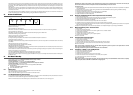
The thermostatic expansion valve meters how much liquid refrigerant is to be allowed into the evaporator section of the refrigeration system.
This is determined by the temperature of the TXV sensing bulb, located on the suction line manifold, at the outlet of the evaporator.
If the bulb senses a warm suction line, more refrigerant is allowed into the evaporator, (common at the beginning of the freeze cycle) and
when the temperature begins to fall, less refrigerant is allowed through. This is why the suction side gauge pressure will decline throughout
the freeze cycle. At the evaporator, the liquid refrigerant released from high pressure, boils off in the low pressure environment and absorbs
heat, thus cooling the evaporator surface and anything near it, such as water.
The low pressure refrigerant vapour then is forced through the heat exchanger where any excess liquid refrigerant boils-off, allowing only
refrigerant vapour to enter the compressor suction tube, where it is recompressed into high pressure, high temperature gas again and the
cycle repeats.
6.2 Water System
A fixed charge of water had been brought into the machine during the harvest or defrost cycle through the float valve.
A pump, running continuously, forces the water to the top of the evaporator, where it is distributed through a water tube and then cascades
down the evaporator surface by gravity. As it flows across the refrigerated evaporators, some of the water will be chilled enough to change
form, turn to ice, and stay frozen onto the evaporator. Most of the water returns to the reservoir, to be sucked back into the pump, and
repumped over the evaporators.