FMIC 260 Machine Specifications - R22 Machines
Model Cond. unit Finish Comp. Water reg.
It/24hr
FMIC 260
Air
Stainless Steel
1.5
400
Water 2400*
Electric
power
Basic Start cons. kWh No. of Amps
Model electr. amps amps Watts per 24hr wires fuse
FMIC 260AS
220-240/50/1
7.5 50 1450 37
3 x 2.5mm
2
20
FMIC 260W 6.5 48 1230 35
Cubes per Harvest: 289 Full
* Subject to variations according to different water and ambient temperature conditions. (Amb. 32°C – Water 15°C)
1 20mm — WATER OUTLET
2 20mm — WATER OUTLET –
WATER COOLED ONLY
3
3
/
4
in GAS WATER INLET
4 CORD SET
Accessories:
KSC 18 — Cube stacking kit
Dimensions:
HEIGHT 530mm (20
7
/
8
in)
WIDTH 800mm (31
1
/
2
in)
DEPTH 600mm (25
3
/
8
in)
WEIGHT 77kg
1. Specification
FMIC 180 Machine Specifications - R22 Machines
Model Cond. unit Finish Comp. Water reg.
It/24hr
FMIC 180
Air
Stainless Steel
1
300
Water 1920*
Electric
power
Basic Start cons. kWh No. of Amps
Model electr. amps amps Watts per 24hr wires fuse
FMIC 180A
220-240/50/1
6 30 980 24
3 x 2.5mm
2
15
FMIC 180W 5.5 28 810 20
Cubes per Harvest: 204 Full
* Subject to variations according to different water and ambient temperature conditions. (Amb. 32°C – Water 15°C)
13
FMIC180
FMIC 260 Machine Specification
R404A Machines
Basic Start
Elec Power
Fuse
Electr. Amps amps Watts
Cons. kWh
Amps
230/50/1 6 30 A 1100 26.4 16 A
FMIC 180 Machine Specification
R404A Machines
Water
Cond unit Finish Comp consumption
Air cooled Stainless steel 1
1
/
4
16 litre per hr
1 20mm — WATER OUTLET
2 20mm — WATER OUTLET –
WATER COOLED ONLY
3
3
/
4
in GAS WATER INLET
4 CORD SET
Accessories:
KSC 25 — Cube stacking kit
Dimensions:
HEIGHT 680mm (26
3
/
4
in)
WIDTH 800mm (31
1
/
2
in)
DEPTH 600mm (25
3
/
8
in)
WEIGHT 100kg
FMIC260
Discharge Suction Evap Ambient
Model Pressure Pressure Temp Temp
FMIC 180 13/15 Bar 1.3 Bar
-10 /
21
°
C
-23
°
C
FMIC 180 18/20 Bar 1.5 Bar
-6 /
32
°
C
-20
°
C
Discharge Suction Evap Ambient
Model Pressure Pressure Temp Temp
FMIC 260 14/17 Bar 1.3 Bar
-10 /
12
°
C
-23
°
C
FMIC 260 18/20 Bar 1.5 Bar
-6 /
32
°
C
-20
°
C
Freeze Cycle R404A Machines
per 24hr
Basic Start
Elec Power
Fuse
Electr. Amps amps Watts
Cons. kWh
Amps
230/50/1 9 49 A 1600 38.4 16 A
Water
Cond unit Finish Comp consumption
Air cooled Stainless steel 2
19.5 litre per hr
per 24hr
FMIC 180 & 260 Electronic Modular Ice Cuber
6. Operation
16
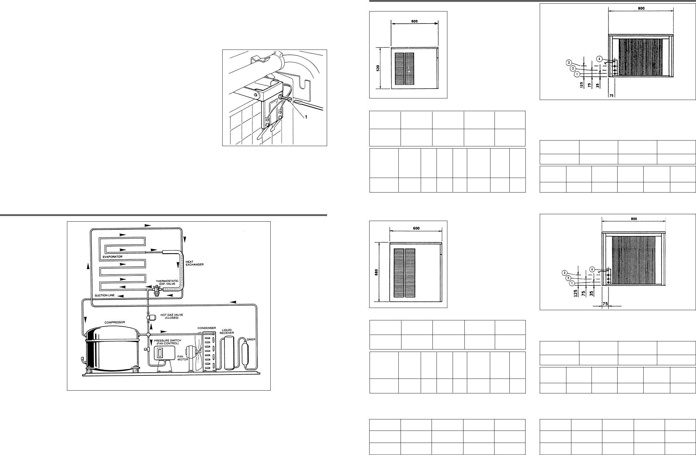
REFRIGERATION SYSTEM SCHEMATIC
6.1 Refrigeration During Freeze
This ice machine employs either air or water as a condensing media, the refrigeration system for either is as follows:
At the hermetic compressor, Refrigerant is compressed into a high temperature, high pressure gas.
This gas contains the heat removed from the evaporator, as well as compressor motor heat. The gas moves through the discharge line
into the condenser, air or water-cooled. If air-cooled, the discharge pressure will change with the heat load and the ambient air temperature.
If water-cooled, the discharge pressure is controlled by the amount of water flowing through the condenser - which is determined by the
water regulating valve.
After the gas is cooled in the condenser, giving up much of its heat, the gas condenses into a high pressure liquid. This liquid travels through
the liquid line to the metering device, a thermostatic expansion valve.
Check operation of the freezing cycle:
a) Compressor is operating.
b) Water pump is operating as seen by water moving through the tygon tube up to
the water distributor at the top of evaporator plate, where water is uniformly
dispensed and cascades down over the egg-crate evaporator and drains back
into the Sump Assembly for recirculation.
4. Remove the evaporator deflector cover temporarily and feel inside the ice cube mould of the egg-crate evaporator, this should feel cold
to the touch, shortly after ice will begin to form.
First freezing cycle will range between 20 and 25 minutes. Longer for temperature above 25°C and shorter when temperature is below 25°C
Average complete cycle time is about 25 minutes.
5. Make sure of correct operation of float valve and water pump.
6. Check for any irregular noise source and if any, eliminate it.
7. Replace plastic cover deflector before harvest cycle.
8. Observe first ice cube harvest.
a) Check operation of N.C. microswitch/magnetic switch on models controlling the
ice maker operation by keeping open the bottom end of the plastic deflector for
more than 30 seconds.
b) Check size of ice cubes; if an adjustment is required thread down or out screw
N. 1 as shown in the illustration.
This screw position determines the distance between the sensor reeds and the
egg-crate evaporator thus keeping the ice cube at a proper thickness.
9. Observe second and third cube harvest.
Check if size and shape combination is correct.
In areas where extreme water problem conditions exist, filtering or purifying equipment
is recommended.
NOTE: If water used is too soft, ‘demineralised’ the ice thickness sensor might
not be able to sense the water on its reeds, thereby it will not switch the unit on
harvest cycle.
A safety system built in the E.C. board switches the unit on harvest cycle whenever
the freezing period gets longer than 40min.
10. Replace all cabinet panels and screws previously removed.
11. Thoroughly explain to owner/user the significant specifications of the ice maker start-up, reset and operation, going through the procedures
in the operating instructions.
Answer all questions about the ice maker by the owner and inform the owner himself of the name and telephone number of the
authorised service agency serving him.


