


Check the second and third cube harvest. Ensure that they are the correct size and make adjustments to the Ice Sensors Fingers as
necessary. In certain areas where there are extreme water problems it may be necessary to fit a filter or purifying equipment.
NOTE. If the water is too soft (demineralized) the Ice Thickness Sensor may not be able to sense the water on its fingers, thereby
not switching the unit onto the harvest cycle. In the event of this occurring a safety system built into the PC Board will automatically
switch the unit into the harvest mode if the freezing period goes beyond 30 or 40 minutes.
NOTE. To ensure a correct operation of the machine the water must have a minimum electrical conductivity level of 20 us.
Open the bottom end of the plastic ice deflector for 30 seconds to check the operation of the magnetic switch. The machine will switch OFF
and the Amber LED will glow to indicate machine OFF at full storage bin. Releasing the deflector will restart the machine in the freezing
mode commencing with the 3-minute delay.
Replace all panels and screws previously removed.
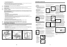
4. Operation
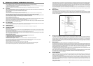
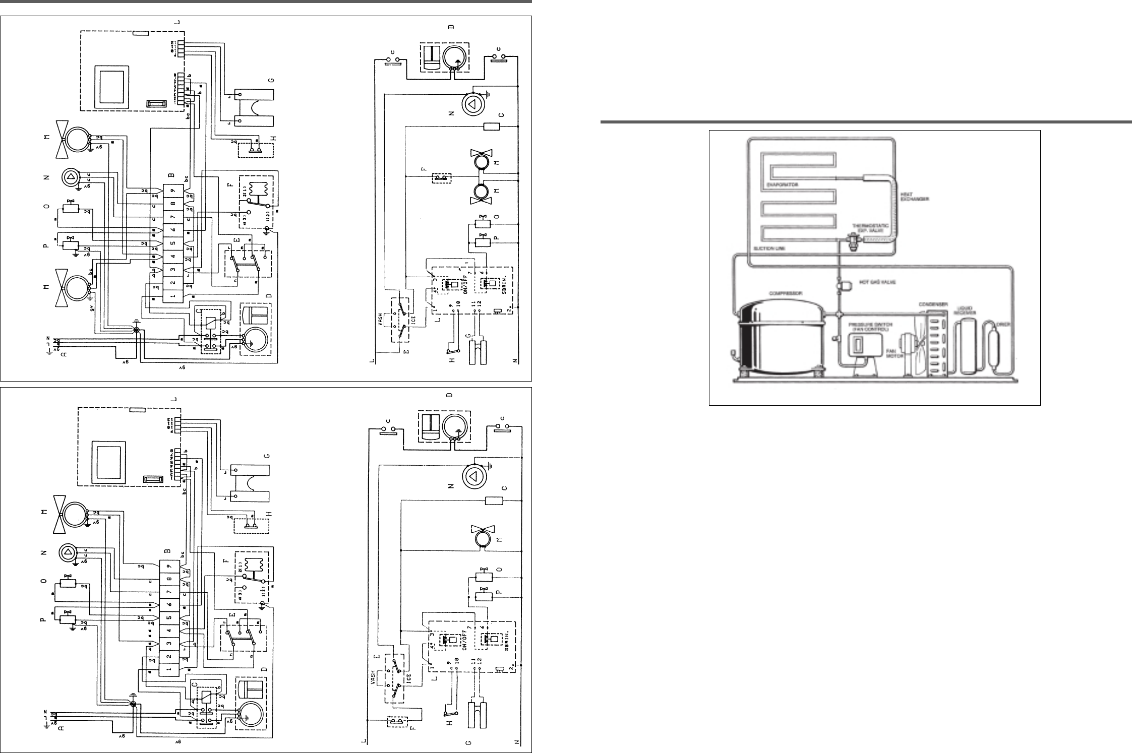
4.1 Refrigeration during freezing.
This ice machine employs either air (standard) or water (optional) as a condensing media, the refrigeration system for either one is as
follows:
The refrigerant metering is by thermostatic expansion valve.
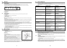
4.2 Water System during freezing.
A combination of the water inlet solenoid valve and water level sensor is used to control the level of the water in the reservoir/sump.
30 seconds from the start of the freeze cycle the water pump starts, forcing water to the top of the evaporator where it is distributed through
the water tube and then cascades over the surface of the evaporator by gravity. Some of the water will turn to ice with the remainder
returning to the water reservoir for redistribution over the evaporator.
4.3 Ice harvest cycle.
When the ice reaches the desired size, as determined by the fingers of the ice thickness sensor, the hot gas bypass valve is energised
allowing the hot gas to warm the evaporator resulting in the ice cube block falling into the storage bin below.
4.4 Water system during ice harvest cycle.
During the harvest cycle, the electric water drain valve is energised opening the drain line. All of the water remaining in the reservoir at the
end of the freezing cycle is pumped, out to drain, through the water solenoid valve during the last 40 seconds of the defrost cycle eliminating
any possible build-up and accumulation of mineral concentration and other impurities in the reservoir.
The water inlet valve is energised for the last 10 seconds whilst the pump is running to allow fresh water to rinse the reservoir.
When the ice cube block is released from the evaporator it causes the deflector to swing open sufficiently to reset the contactor of the
magnetic switch which, via the PC Board, de-energises the water drain valve initiating a new freezing cycle.
The harvest/defrost cycle lasts between 1 and 2 minutes.
4.5 Control sequence.
At the start of the freezing cycle the contacts of the magnetic switch, mechanically operated by deflector cover, are closed via the PC Board,
thereby closing the circuit to the main contactor coil and consequently the compressor, fan motor and after 30 seconds the water pump.
As the ice reaches the thickness required the film of water flowing over it makes contact with the ice thickness sensor fingers (energised at
low voltage). If contact is maintained for more than 10 seconds a relay on the PC Board is energised controlling simultaneously the hot gas
valve and the water drain valve.
NOTE: In the event of failure of the ice thickness sensor, the PC Board automatically turns the unit into the defrost cycle when the
freezing cycle reaches 30 or 40 minutes depending on the operation of the fan motor during the freezing cycle.
At this point the unit initiates the defrost cycle. The hot gas circulating into the evaporator serpentine causes a slight melting of the ice cube
7
REFRIGERATION SYSTEM SCHEMATIC
22
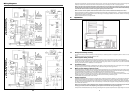
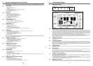
Wiring Diagrams
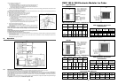
180 + 260 Wiring Diagram
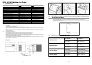
Air Cooled 220 V. 50 Hz 1 ph
A – Power
B – Terminal block
C – Contactor
D – Compressor
E – Toggle switch
F – Pressostat
G – Ice sensor
H – N.C. Microswitch /
Magnetic Switch
L – Electronic card
M – Fan motor
N – Motor pump
O – Water drain valve
P – Hot gas valve
Colour of the Cables
m– Brown
bc– Light blue
gv– Yellow green
b – White
n–Black
r–Red
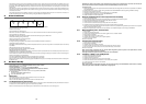
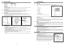
180 + 260 Wiring Diagram
Water Cooled 220 V. 50 Hz 1 ph
A – Power
B – Terminal block
C – Contactor
D – Compressor
E – Toggle switch
F – Pressostat
G – Ice sensor
H – N.C. Microswitch /
Magnetic Switch
L – Electronic card
M – Fan motor
N – Motor pump
O – Water drain valve
P – Hot gas valve
Colour of the Cables
m– Brown
bc– Light blue
gv– Yellow green
b–White
n–Black
r–Red