


block releasing it from the mould. Once released the ice block drops into the storage bin below and breaks into individual cubes, in the
process it moves the deflector plate forwards. The defector has on its side a magnetic switch that when it moves forward it opens and closes
the contacts. This motion deactivates the relay contacts that control the hot gas and water drain valve allowing the unit to start a new
freezing cycle.
When the ice bin is full of ice, the last batch of ice released from the evaporator cannot continue into the bin and so it stops the deflector from
returning to its position. With the magnetic switch contacts remaining open for more than 30 seconds the entire unit stops with the glowing
of the Amber bin full LED.
The machine will restart when the deflector returns to its normal position provided the machine has been of for more than 3 minutes, if not
the start will be delayed for 3 minutes with the blinking of the green Machine In Operation LED.
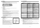
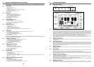
5. Alarm Conditions
Power On.‘Green’. Bin Full/ Washing. ‘Amber’. High Pressure. ‘Red’.
Machine in Operation ‘Green’. Alarm ‘Red’. Reset / Washing. ‘Push Button’.
The two Red LED’s are glowing constantly.
Condenser Sensor faulty.
The two Red LED’s are blinking slowly.
Water Error. The water level inside the reservoir is to low after 3 minutes from start of the water inlet valve being activated.
The two Red LED’s are blinking fast.
Reset Mode. Charging water through the Water Solenoid Valve after tripping OFF on Water Error.
The Red Alarm LED is glowing continuously.
Harvest cycle longer than 3 minutes 30 seconds.
The Red Alarm LED is blinking slowly.
Too High Condensing Temperature: The Condenser Sensor detected a temperature above 65°C.
The Red Alarm LED is blinking fast.
Reset Mode: Condenser Sensor sensing condenser temperature below 50°C, fan motor in operation for 3 minutes then back on to Start Up
Cycle Mode.
Red High Pressure LED is glowing continuously.
Too High Discharge Pressure, exceeding 33 bar (460 PSI).
Red High Pressure LED is blinking fast.
RESET MODE: After pushing the Red Reset Button of the Pressure Control (located at the rear of the machine) firstly the fan motor runs for
3 minutes then back on to the Start Up Cycle Mode.
The PC Board also checks the maximum time of the freeze cycle that may change according to the operation of the fan motor during the
freezing cycle (relative to room temperature).
Fan motor in ON/OFF Mode: Maximum Freeze Cycle length equal to 30 minutes.
Fan motor ON All of the time: Maximum Freeze Cycle length equal to 40 minutes.
Whenever the machine remains in the Freezing Cycle for the Maximum time ( 30 or 40 minutes) the PC Board moves the unit directly into
the Harvest Cycle.
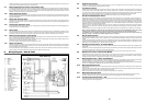
6. PC Board Set Up
The PC Board can be set up for Manual Reset Mode with the Jumper In Place.
Manual Reset Mode. (Jumper in place)
To Restart the Machine it is necessary to Push the Reset Button.
The PC Board can be set up for Automatic Reset Mode with the Jumper Out Of Place.
Automatic Reset Mode. (Jumper out of place)
The Automatic Reset Mode is activated only for the following ALARM CONDITIONS.
•
WATER ERROR
•
TOO HIGH CONDENSING TEMPERATURE
•
TOO LONG HARVEST CYCLE.
6.1 Water Error
The machine remains in OFF mode for 30 minutes then it tries to re-fill with water.
Fills with water: Machine remains in operation.
Fails to fill with water: Machine again in the OFF mode for a further 30 minutes.
6.2 Too High Condensing Temperature
As soon as the temperature registered by the Condenser Sensor is above 50°C, the PC Board starts up firstly the condenser fan motor for
3 minutes then the entire machine through the normal Start UP Cycle Mode.
After the 3 minutes 30 seconds of the Harvest Cycle, the PC Board moves the machine into a new Freezing Cycle.
8
CAUTION: If the factory seal is broken on the replacement drier, exposing it to the atmosphere for more than a few minutes, the
drier will absorb moisture from the atmosphere and lose substantial ability for moisture removal.
To replace the drier:
1. Remove the factory seals from the replacement drier and install the drier in the refrigerant lines with the arrow positioned in the direction
of the refrigerant flow.
2. Solder the drier into the lines, two places, taking precautions NOT TO OVERHEAT the drier body, during installation soldering.
3. Purge the system and check for leaks.
4. Thoroughly evacuate the system to remove moisture and non- condensables.
5. Charge the system with refrigerant, by weight. SEE NAMEPLATE.
6. Replace and attach front and left side panel.
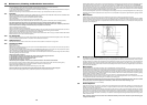
9.10 Removal and Replacement of the Evaporator Plate Assembly
1. Remove front and top panels.
2. Store refrigerant charge in liquid receiver and isolate parts to be opened from the rest of the system.
3. Disconnect water distributor tube above the evaporator plate and remove it.
4. Unsnap and remove evaporator cover deflector.
5. Loosen and remove all screws securing the evaporator frame to the chassis.
6. Unsolder and remove the refrigerant lines at the top of the evaporator plate to be replaced.
7. Remove nuts at top and left and right side of the evaporator to remove top and side trimming that make-up the frame of the evaporator
plate. The evaporator plate is now free.
To replace the evaporator plate, reverse the removal procedures. See nameplate. Weight in proper charge of R22/R404A.
9.11 Water Regulating Valve - Water Cooled
1. Shut off water.
2. Remove front and right side panel.
3. Unscrew water inlet fitting connection at the water regulator valve to condenser bracket.
4. Purge system of refrigerant.
5. Unscrew fitting connection at outlet of valve.
6. Unsweat valve connection from ‘T’ joint on system liquid line.
7. Remove valve from machine.
Reverse to reassemble.
9.12 Thermostatic Expansion Valve
1. Remove front, top and right side panels.
2. Purge system of refrigerant.
3. Unsweat valve at inlet, equaliser, and outlet.
4. Remove insulation from valve bulb, remove mounting straps and valve from cabinet.
5. Place new valve bulb in same place as old valve, secure with straps, and reinsulate.
Reverse to reassemble.
NOTE: Always install a replacement drier, any time the sealed refrigeration system is opened. Do not replace the drier until all
other repair or replacement has been completed.
Thoroughly evacuate the system to remove moisture and non-condensables.
9.13 Fan Motor or Blade - Left and Right Side
1. Remove left or right side service panels.
2. Remove screws and fan motor shroud.
3. Unplug fan motor to be removed.
4. Remove fan motor bracket from upper tie rod of unit chassis.
5. Remove fan blade from motor. Note location on motor shaft, and hub position.
6. To also replace fan motor, remove it from bracket.
Reverse to reassemble.
NOTE: When replacing a refrigeration component, the exact refrigerant charge must be WEIGHED or metered into a completely
evacuated system, because the FMIC is a CRITICALLY charged system.
21