


10) Connect the
3/4" Feeding pipe
(supplied) to the
machine and to the
cold drinking water
supply line. It is
advisable to install a
shut-off valve (not
supplied) to the
water feed pipe. If
the feed water
contains impurities,
the installation of a
filter system is
recommended. If the
water is particularly hard, i.e.
rich in minerals and their derivatives, the
application of a suitable water filter is
recommended, preventing any scale
deposits blocking the water circuit of the
machine (Fig.18).
11) Fit the flexible drain pipes to the
icemaker and the storage bin ensuring
there is adequate fall on the pipes to avoid
the drain water backing up. For a perfect
water outlet from the machine a minimum
incline of 3% of the pipes is advisable.
Check also that the pipes are not throttled
or siphoned. It is advisable that the pipes
discharge in an open vented drain (Fig.18).
Warning!
It is expressly forbidden for the users of
the equipment to carry out the following
operation or those marked by the sym-
bol, Such operations must be performed
exclusively by qualified personnel.
1. Electrical connections
2. Water mains connections
3. Machine installation
4. Machine test run
5. Repairing machine components and parts
6. Disassembly of machine and/or
components
7. Adjustment and setting procedures
8. Machine cleaning and maintenance relative
to the following parts and components:
Electrical, Electronic, Mechanical,
Cooling System
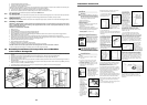
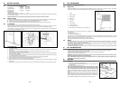
Models 200 KG, 300 KG,
The icemaking machines
are approved by VDE, GS
and the relative symbols
are put on the packing,
serial plate and body of
the machine (Fig.10).
Note
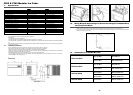
Before installing the machine make
sure that:
a) the room temperature must not fall
below 10˚c (50˚F) or above (100˚F).
b) the water conductivity value must not
be below 10 µs/cm.
c) the main water temperature must not
fall below 5˚C (40˚F) or above
35˚C (95˚ F).
2
OUR PRODUCTS ARE GOVERNED BY EC
LOW VOLTAGE DIRECTIVE 73/23/EEC -
EMC - 89/336/EEC AND THE COVER OF
THE MANUAL IS MARKED ACCORDINGLY.
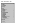
preface
general specifications
installation
1
3) Clean the inside of machine and storage bin by
means of a warm water and sodium-bicarbonate
dampened sponge; rinse with plain water and dry
thoroughly.
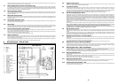
4) Locate the icemaker and
the storage bin in the final
place, making sure that the
two are perfectly level, in
order to obtain an even
distribution of the water all
over the evaporator and a
uniform filling of the cube
plate (Fig.13).
The storage bin is equipped
with adjustable feet, which
allow for easy levelling and
sufficient height for cleaning
under the machine.
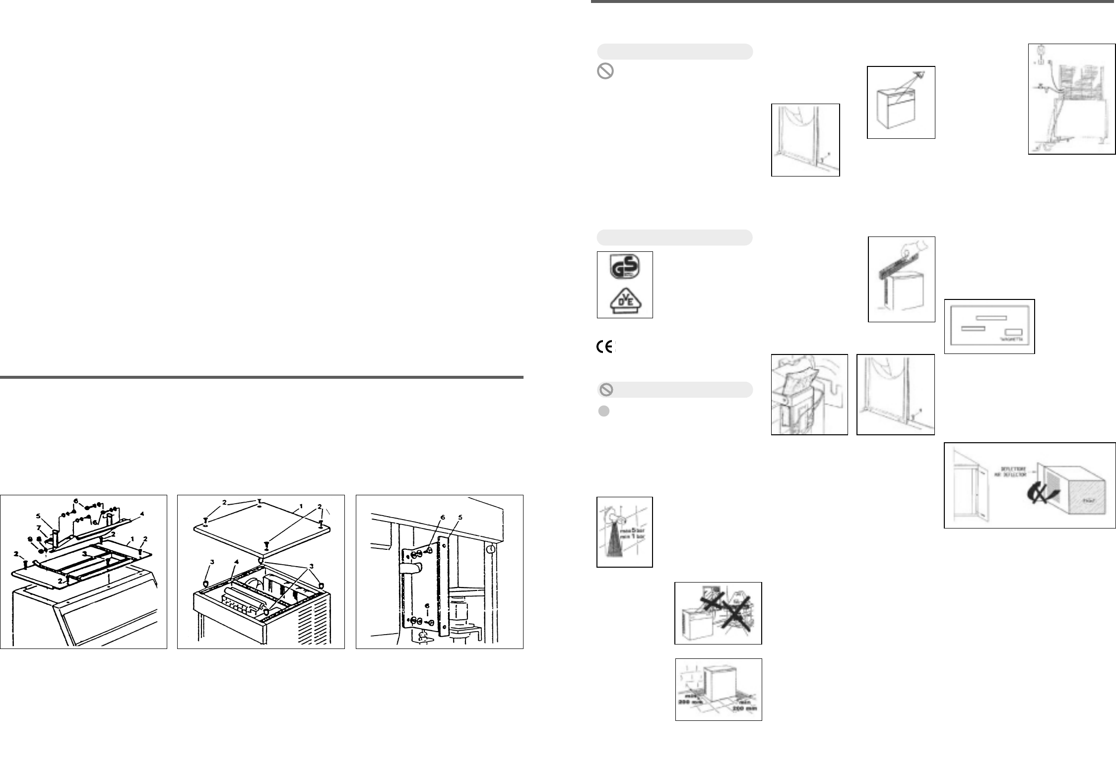
5) Unlock the sensor and the baffle by removing
the transit packaging 1and tape 2, which have
been applied to avoid any damage during
transportation (Fig.16 & Fig.17).
6) The icemaker has been designed for coupling
with another icemaker, which can be installed on
the top of the first one. For this installation, a kit
can be supplied upon request. It contains all
necessary assembling instructions.
7) Do not put the machine in a dusty
environment as this could cause a fast build up of
dust etc, therefore effecting the efficient working
of the condenser (only for air-cooled models).
8) Never keep food, bottles or other things in the
bin in order to avoid the stored ice becoming
tainted.
9) Connect machine to the water supply first and
then to a suitable electricity supply.
2) Match the icemaker to
its storage bin, fixing them
with the two screws
supplied with the machine
(Fig.20).
Before bringing the icemaker into action
perform the following operations:
e) machine is
away from
sources of heat
and in a
sufficiently
ventilated area.
A distance of at
least 20cm must
be allowed
between the
sides, back and
the walls of the
machines
(Fig.12, Fig.14).
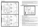
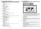
12) Connect the
machine to the
electricity supply
after having
checked that the
voltage corresponds
to that on the plate
on the rear panel of
the machine (Fig.5).
13) Air deflector installation. (Fig.24) The
deflector has to be installed in order to
prevent the re-circulation of hot air to the
condenser.
The maximum voltage variation should not
exceed ± 6% of that stated on the rating
plate. A fused isolator must be included in
the electrical circuit to the machine, with its
own bipolar main switch at least 3 mm. of
contacts opening. The machine should be
connected to a suitable power supply with
earth terminal.
d) the main water pressure
must not fall below
1bar. (14 PSI) or above
5 bar. (70 PSI). If
pressure is above 5 bar.
a pressure regulator
should be fitted to
the water supply to the
machine (Fig.11)
f) the machine will
not work with
demineralized
water.
Fig 10.
Fig 11.
Fig 12.
Fig 14.
Fig 1.
Fig 20.
Fig 13.
Fig 16.
Fig 17.
Fig 18.
Fig 5.
Fig 24.
1) Check that ice cuber has
not been damaged during
transportation (Fig.1)
Installation Instructions
5
5. Check and tighten all bolts and screws.
6. Check for water leaks and make corrections.
7. Check the bin control to test shut-off.
Holding the evaporator deflector in open Position for more that 30secs, should cause the ice maker to shut-off at the end of harvest cycle.
Once the evaporator deflector is released in its closed position, the ice maker will restart.
8. Check cube size, adjust if required through setting screw of ice thickness control sensor.
9. With unit out of operation, clean the condenser using vacuum, cleaner, whisk broom or brush.
Instruct customer to clean condenser frequently DO NOT USE A WIRE BRUSH.
11.2 Ice Storage Bin
The interior liner of the bin is in contact with a food product, ice, and should be cleaned regularly. Once a week clean with soap and water,
and after that a hot water rinse and dry thoroughly. Commercial food grade sanitisers are available, and may be used.
11.3 Cabinet Exterior
Wipe clean unit and bin cabinet exterior with a clean cloth or disposable paper wipers, soaked in warm water with mild detergent solution.
11.4 Cleaning - Ice Maker
WARNING - Ice Machine Cleaner contains Phosphoric and Hydroxyacetic acids. These compounds are corrosive and may cause
burns. If swallowed, DO NOT induce vomiting. Give large amounts of water or milk. Call physician immediately. In case of
external contact, flush with water.
KEEP OUT OF THE REACH OF CHILDREN.
1. Empty bin of ice.
2. Remove front panel.
3. Switch the Master switch power line and Unit Toggle switch OFF
4. Remove evaporator cover deflectors by lifting-up and pulling-up.
5. Switch the Master switch power line ON. Pour 200grs of Ice Machine Cleaner into the reservoir and put the unit toggle switch to
WASH position. Run unit for 15 minutes.
6. Using correct brush clean the interior of each evaporator egg-crate using the cleaning solution from the water reservoir.
7. Switch to OFF, remove the drain plug from the water reservoir to flush cleaning solution out of the reservoir. Replace the plug and allow
fresh water through float valve to fill-up the reservoir to thoroughly rinse it.
8. Repeat the reservoir flushing out two or three times.
9. Switch the toggle switch to ICE position.
10. Replace the evaporator cover deflector and front panel.
11. Check the next batch of cubes to be sure all the cleaner has gone (no sour taste).
CAUTION: DO NOT use ice cubes produced from the cleaning solution. Be sure none remains in the bin.
12. Pour hot water into the storage bin to melt the cubes, and to also clean the bin drain.
24
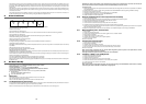
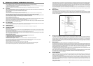
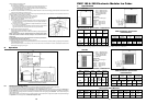
12. Assembly Instructions of Conveyor Kits for Ice Machines
to be fitted on Storage Bin
1. Fit the cover kit on the storage bin of 300kg (as indicated in Fig. 1) and put the lower ice maker on the bin as indicated in the instruction
manual.
2. Remove the cover and the 4 bushes (No.3) of the lower ice maker (Fig. 2), then apply the support gaskets No.4.
3. Remove the front and the 2 lateral panels of the lower ice maker and fit the conveyor support No.5 (Fig. 3).
4. Fit the conveyor kit (No.7 - Fig. 4).
5. Apply the upper ice maker after having removed the front and the 2 lateral panels and fix it to the lower ice maker through 2 screws on
the lateral edges.
6. Hook the shoot conveyor (No.10 - Fig. 6) at the edge of the upper ice maker water pan and fix it to the vertical conveyor No.7, previously
fitted on the lower ice maker (as indicated on Fig. 6).
7. Connect the upper ice maker micro to the conveyor kit as explained on Fig. 5 and on the enclosed wiring diagram.
8. Place back the panels previously removed.
Fig.1
Fig.2 Fig.3