


2-4
2. The rethermalizer must be stabilized by installing restraining chains on units equipped with
casters or anchor straps on units equipped with legs. Follow the instructions shipped with the
casters/legs to properly install the chains or straps.
3. Level rethermalizers equipped with legs by screwing out the legs approximately 1 inch then
adjusting them so that the rethermalizer is level.
4. For rethermalizers equipped with casters, there are no built-in leveling devices. The floor where
the rethermalizer is to be installed must be level.
DANGER
Do not attach an apron drain board to this unit. The appliance may become
unstable, tip over, and cause injury. The appliance area must be free and clear of
combustible material at all times.
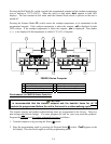
5. Connect the water hose to the fitting at the rear of the unit.
NOTE 1: The hose comes with a quick-disconnect coupling. The quick disconnect may be at-
tached to the rethermalizer or to the water supply line, or it may be left off entirely, whichever
you prefer. Whichever of the options is chosen, Teflon thread-seal tape or Loctite™ PST56765
or equivalent thread sealer must be used when installing the fittings.
NOTE 2: Either hot or cold water may be connected to the unit. Connecting to hot water will
minimize the amount of time required to bring the unit to boil when filling with fresh water.
However, on FBCR18 units, connecting to hot water will lower the efficiency of the chill fea-
ture.
NOTE 3: In order for the water level sensors to work properly, a certain amount of mineral con-
tent in necessary in the water. For that reason, purified, deionized, or highly filtered water
should not be used.
4. Connect the desired drain plumbing to the 1¼” drain valve.
5. Test the equipment electrical system by plugging the power cord into a grounded 120VAC outlet
and pressing the computer’s ON/OFF button.
°
-Lo or cycl should appear in the display.
6. Turn the computer off. Verify that the display is blank.
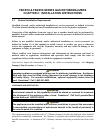
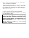
7. Verify that the minimum and maximum incoming gas pressures for the type of gas to be used are
in accordance with the accompanying table.
Incoming Gas Pressures
Gas Minimum Maximum
Natural
6" W.C.
1.49 kPa
14.93 mbar
14" W.C.
3.48 kPa
34.84 mbar
LP
11" W.C.
2.74 kPa
27.37 mbar
14" W.C.
3.48 kPa
34.84 mbar