


6-5
6.6.2 Replacing the Temperature Probe
1. Unplug the rethermalizer.
2. Drain the cookpot.
3. Remove the screws from the upper corners of the control panel and swing the panel open from
the top, allowing it to rest on its hinge tabs.
4. Remove the cover from the component box by removing the three screws along its bottom edge.
5. Cut the temperature probe wires an inch or so from the 12-pin connector. Leave the cut off wires
in the connector.
6. Remove the temperature probe and install replacement, resealing with Loctite
®
PST56765 pipe
thread sealant or equivalent. Be careful not to damage the leads when installing the new probe.
7. Thread the leads through opening in the bottom of the component box and through the insulating
sleeve.
8. Unplug the 12-pin connector from the interface board. Using a pin pusher, remove the cut off
pieces of wire from the connector one at a time, and insert the corresponding wire from the new
part.
9. Reattach the 12-pin connector to the interface board, replace the component box cover, and close
and secure the control panel.
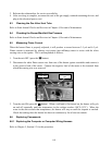
6.6.3 Replacing the Interface Board
1. Unplug the rethermalizer.
2. Remove the screws from the upper corners of the control panel and swing the panel open from
the top, allowing it to rest on its hinge tabs.
3. Detach the grounding wire from the computer, unplug the 15-pin connector from the interface
board, and remove the control panel from the unit by lifting it up and out of the hinge slots in the
control panel frame.
4. Disconnect the 12-pin connector from the interface board.
5. Mark the yellow water level sensor wires and disconnect them from terminals J3 and J5.
6. Remove the nuts in each corner of the interface board and carefully pull the board off the
mounting studs, being careful not to dislodge the spacers on the studs.
7. Position the replacement board on the studs and replace the four nuts.
8. Reconnect the water level sensor wires and the 12-pin connector to the interface board.
9. Remount the control panel to the control panel frame and reattach the grounding wire.