


6-2
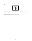
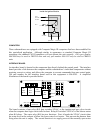
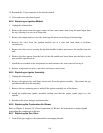
TD
Out to
Gas Valve
To Alarm
25 V +
25 V GND
HV
Ignition Wire Flame Sensor
Coil
Inside the Ignition Module
COMPUTERS
These rethermalizers are equipped with Computer Magic III computers that have been modified for
this specialized application. Although similar in appearance to standard Computer Magic III
computers, the standard CM III computers will not operate the unit correctly. Only part number
806-8063 may be used in FBCR18 units and only part number 806-9352 may be used in FBKR18
units.
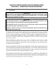
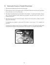
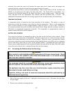
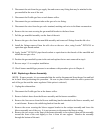
INTERFACE BOARD
An interface board is located in the component box directly behind the control panel. The interface
board provides a link between the computer and the rethermalizer’s individual components without
requiring excessive wiring, and allows the computer to execute commands from one central point.
The part number for the interface board used in this equipment is 806-9295. A simplified
illustration of the board is provided below.
HEAT
WATER
LATCH
J4
J4
HI
LO
J3
K6
WATER
K3
LATCH
+15V
GND
J1
K1
OPT
B/L-R
K2
OPT
B/L-L
K5
BLOWER
K4
HEAT
J2
ORANGE
RESISTOR
The board contains a heat relay (K4) that switches 24VAC to the ignition and gas valve circuits
when the computer heat logic circuit calls for heat. Relay K5 switches 120VAC to the blower motor
when K4 closes. The water relay (K6) has two functions. First, it breaks the 24VAC circuit when
the water level in the cookpot is below the lower water level sensor. This prevents the burners from
firing when the unit is empty. The second function is to supply power to the normally open water