7-5
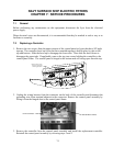
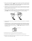
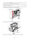
5. Remove the nuts and machine screws that secure the element to the tilt plate assembly and pull
the element out of the frypot. NOTE: Full-vat elements consist of two dual-vat elements
clamped together. For full-vat units, remove the element clamps before removing the nuts and
machine screws that secure the element to the tilt plate assembly.
6. If applicable, recover the probe bracket and probe from the element being replaced and install
them on the replacement element, then install the replacement element in the frypot, securing it
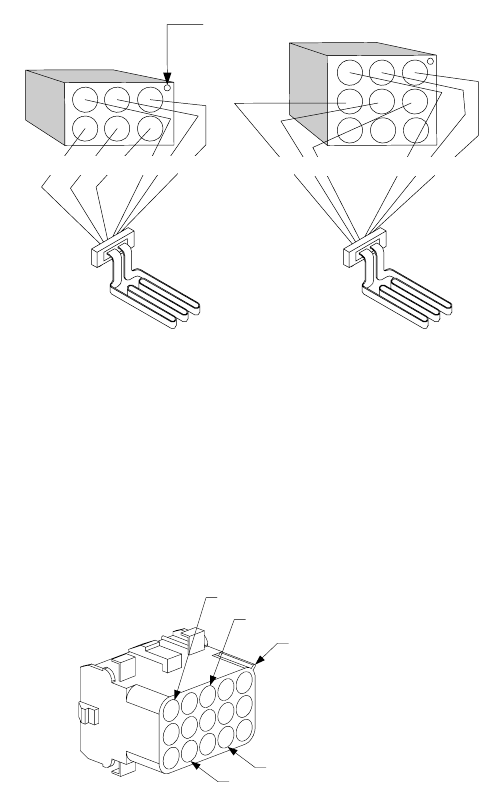
with the nuts and screws removed in Step 5.
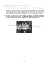
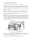
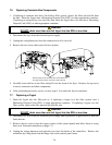
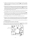
7. Route the element leads through the wire loom to prevent chafing and press the pins into the
connector in accordance with the diagram below, then close the connector to lock the leads in
place. NOTE: It is critical that the wires be routed through the loom to prevent chafing.
1
4
2
5
3
6
1
4
2
5
3
6
789
5R 4R6R 1R2R3R
Pip marks Position 1
5L 4L6L 1L2L3L
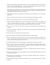
8. Insert the element connector into the receptacle on the front of the contactor box, ensuring that
the latches lock.
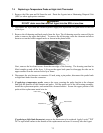
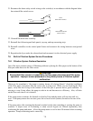
9. If disconnected in step 2, insert the temperature probe leads into the wiring harness connector
(see illustration below). For full-vat units or the right half of a dual-vat unit, the red lead goes
into position 6 and the white into position 7. For the left half of a dual-vat unit, the red lead goes
into position 12 and the white into position 13. NOTE: Right and left refer to the fryer as
viewed from the rear.
Rib marks Position 1
6
7
12
13
10. If disconnected in step 2, reconnect connector C6 of the wiring harness.
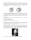
11. Reconnect the element springs and lower the element back down onto the basket rack.
12. Reinstall the tilt housing and back panels, reposition the fryer under the exhaust hood, and
reconnect it to the electrical power supply.


