


Part # 4523974 (11/07) Page 13
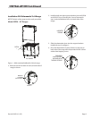
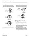
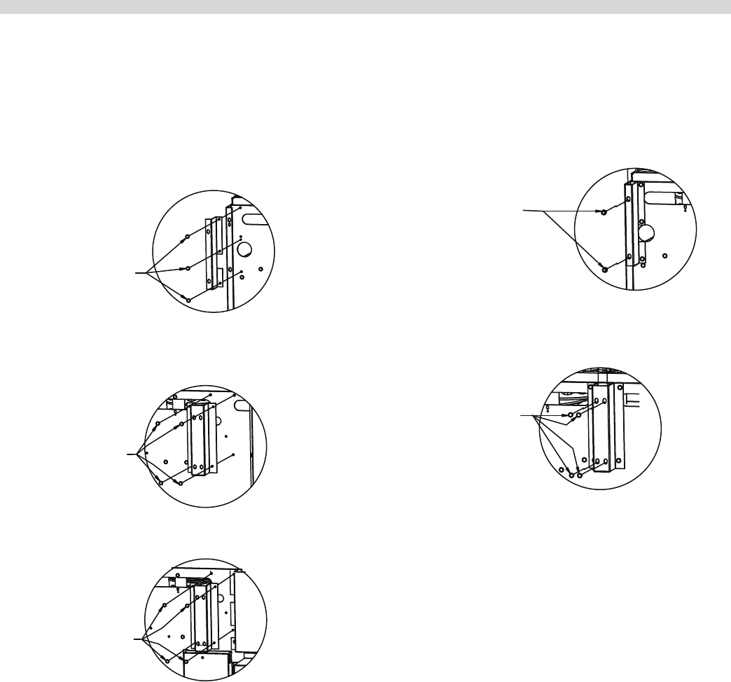
2. Install the left and right support brackets (part # 4523226
and 4523227) using the 2 screws removed in step 1
(detail I) and one additional screw on both sides of the
range, and center support bracket (part # 4523282) with
the four screws removed in step 1 (detail II).
INSERTED
SCREWS
DETAIL I
ALL 60" MODELS
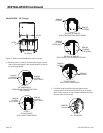
4 INSERTED
SCREWS
4 INSERTED
SCREWS
DETAIL II
FOR 60" RANGES
WITH STANDARD OVEN
DETAIL II
FOR 60" RANGES
WITH CONVECTION OVEN
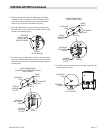
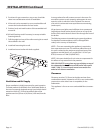
3. Slide the salamander down into the support brackets
installed in step 2, see gure 3.
4. Once the salamander is in place, fasten it to the unit on
both sides of the range with the provided #14B x 5/8 hex
washer head tapping screws (detail I) and the center to the
support bracket using 4 of the provided screws (detail II).
DETAIL I
ALL 60" RANGES
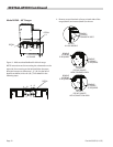
PROVIDED
#14B x 5/8 HEX
WASHER HEAD
TAPPING SCREWS
4 PROVIDED
SCREWS
DETAIL II
ALL 60" RANGES
Wall Or Counter Mounted Salamanders
Model UIRC
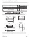
1. Clearance from combustible construction must be six
inches (6”, 152mm) minimum at the rear and six inches
(6”, 152mm) minimum at both sides.
The appliance shall be located with respect to building
construction and other equipment so as to permit access
to the appliance. Such access and clearance may be
necessary for service and cleaning.
2. Counter models are furnished with 4” (102mm) legs.
Level the unit with a carpenter’s level and make minor
adjustments with the threaded leg feet. Ensure that the
counter top can support the weight of the appliance
prior to installation and is comprised of non-combustible
material.
INSTALLATION Continued