


Part # 4523974 (11/07) Page 7
INSTALLATION Continued
Gas Connections
All xed (non mobile) appliances MUST be tted with a
manual gas cock upstream of the appliance to provide a
means of isolation for servicing or cleaning purposes. A
union or similar means of disconnection must be provided
between the gas cock and the appliance.
A manually operable valve must be tted to the gas supply
to the kitchen to enable it to be isolated in an emergency.
Whenever practical, this shall be located either outside the
kitchen of near an exit in a readily accessible position.
Where it is not practical to do this, an automatic isolation
valve system shall be tted which can be operated from a
readily accessible position or near to the exit.
At locations where the manual isolation valve is tted or
the automatic system can be reset, a notice MUST be tted
stating:
“ALL DOWNSTREAM BURNER AND PILOT VALVES MUST
BE TURNED OFF PRIOR TO ATTEMPTING TO RESTORE THE
SUPPLY. AFTER EXTENDED SHUT OFF, PURGE BEFORE
RESTORING GAS.”
Before assembly and connection, check gas supply.
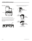
A. The type of gas for which the unit is equipped is stamped
on the rating plate located on the lower front panel
simply remove the drip tray for easy access. Connect a
unit stamped “NAT” only to natural gas; connect those
stamped “PRO” only to propane gas.
B. If it is additional equipment or a replacement have a
qualied gas technician check the gas pressure to make
certain that existing gas facilities (meter piping, etc.)
will supply gas to the unit with no more than 1/2” water
column pressure drop.
NOTE: When checking pressure, be sure that all other
equipment on the same gas line is on. A pressure regulator
is supplied with US Range Infra-Red Broilers. The regulator
is preset to deliver gas at the pressure shown on the rating
plate.
C. The appliance and its individual shut o (supplied by
others) must be disconnected from the gas supply piping
system during any pressure testing of that system at
pressures in excess of 1/2” psi (3.45 kPa).
D. The appliance must be isolated from the gas supply
piping system by closing its individual manual shut o
valve (supplied by others) during any pressure testing of
the gas supply piping system at test pressures equal to or
less than ½ psi (3.45 kPa).
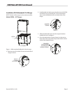
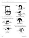
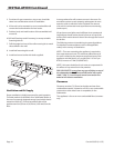
E. The gas supply connection is made either at the top left
rear or lower rear right corner, depending on how the
unit was ordered. A readily accessible approved type of
hand valve should be installed on each supply line. Test
for leaks – DO NOT USE ANY OPEN FLAME.
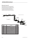
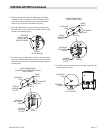
F. A pressure tap plug is supplied with the units and it is
installed on the manifold. The drip tray must be removed
to use the pressure tap. The gas pressure must be
checked when the unit is installed, to insure that the unit
gas pressure is the same as specied on the rating plate.
If necessary, pressure adjustments must be made at the
supplied pressure regulator.
NOTE: the pressure regulator is located at the top left rear or
bottom right rear of the salamander.
G. If it is a completely new installation, have a qualied gas
technician check meter size and piping to ensure that
the unit is supplied with a sucient amount of gas at the
specied pressure for unit operation.
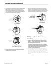
H. Make certain that the new piping, joints and connections
have been made in a clean manner and have been
purged, so that the piping compound, chips, etc, will not
clog pilots, valves and/or controls. Use pipe joint sealant
that is resistant to liqueed petroleum gas.
WARNING Check gas connections for leaks. Use a soap
solution or similar means. DO NOT USE AN OPEN FLAME!