


Part # 4523974 (11/07)Page 14
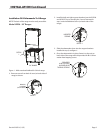
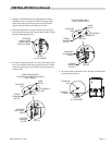
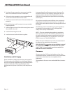
3. Provisions for gas connections, top or rear, should be
taken into consideration at time of installation.
4. If the unit is to be mounted on a non-combustible wall
contact the local authorities for local codes.
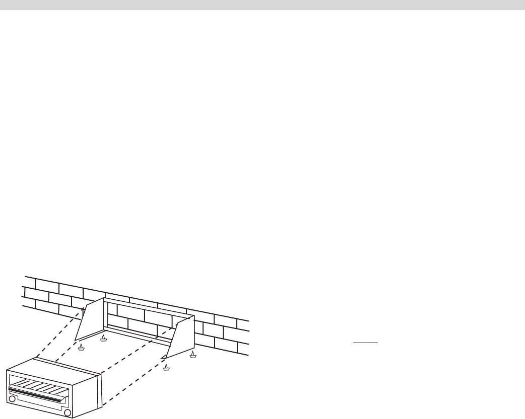
5. Position, level, and mark location of the assembled wall
mount kit.
6. Drill wall (locating studs if necessary) to accept suitable
fastening devices.
7. Drill the angle iron bars of the wall mounting kit to match
those drilled in the wall.
8. Install wall mounting kit to wall.
9. Install and secure broiler with bolts supplied.
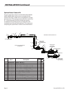
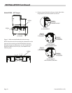
Ventilation and Air Supply
Proper ventilation is highly important for good operation.
The ideal method of ventilation for a Salamander Broiler is
the use of a properly designed canopy hood which should
extend six inches (6”, 152mm) beyond all sides of the
appliance and six (6) feet six (6) inches (1981mm)from the
oor.
A strong exhaust fan will create a vacuum in the room. For
an exhaust system to work properly, replacement air must
enter the room in which the vent is located. The amount
of air which is exhausted must equal the amount entering,
(make-up air).
All gas burners and pilots need sucient air to operate and
large objects should not be placed in front or on top of the
broiler which would obstruct the air ow through the front of
the broiler.
The following notes are intended to give general guidance.
For detailed recommendations, refer to the applicable
code(s) in the country of destination.
NOTE 1: The room containing the appliance is required to
have a permanent air vent. The minimum eective area of
the vent is related to the maximum rated heat input of the
appliance and shall be 4.5 cm per kW (2.04 X 10⁻⁴ in per
BTU/H) in excess of 7 kW. (23,900 BTU/H).
NOTE 2: Air vents should be of such a size to compensate for
the eects of any extract fan in the premises.
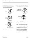
FOR YOUR SAFETY never place any type of object on top of
the salamander broiler. The top of the broiler will exceed
1000° F (538° C). It could cause severe burns and/or re
and also will obstruct ventilation.
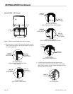
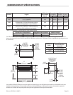
Clearances
Clearance must be 6” (152mm) at the sides and rear from
combustible material. A clearance of 0.0” to non combustible
construction at the sides & rear is acceptable, for the
Salamander.
This appliance is for use on non-combustible oors/counters
only.
INSTALLATION Continued