


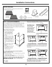
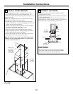

When necessary, the hood may be installed so that it is
supported by the soffit.
• The soffit should be constructed with 2 x 4’s.
• Determine the installation location.
• Continue the centerline forward on the bottom of the
cabinet or soffit.
Alternate Mounting Method
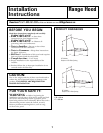
INSTALL HOOD TO SOFFIT OR
BENEATH CABINETS
Installation Instructions
15
4
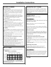
IMPORTANT: Framing must be capable of
supporting 100 lbs (45.3 kg)
• Mounting screws must be secured to 2 x 4 studs
(Dim. “A”) at locations shown in the above chart.
• Allow minimum opening (Dim. “B”) to accommodate
the duct transition in the soffit.
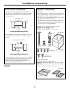
Cut a 10¾” x 8-7/16” hole through bottom of soffit or cabinet
for duct transition as shown.
B
A
A
C
2-3/8"
8-7/16"
5-3/8" 5-3/8"
Rear Wall
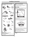
1 Ft = 0.3 m
1” = 2.5 cm
7-1/16"
14-1/2"
C
14-1/2"
12"
29-7/8"
2-9/16"
2-1/4"
2-3/8"
8-7/16"
10-3/4"
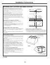
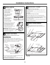
IMPORTANT: For additional support and to minimize
vibration during operation, we strongly recommend that
the hood also be secured to the back wall with wall
fasteners.
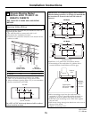
Top View, Front Side
30” Models
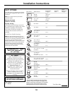
• Drill four 1/8” pilot holes in locations shown.
– If mounting to the underside of a cabinet with a
recessed bottom, install shims to fill the gap.
SKIP THIS STEP IF USING WALL MOUNTING
METHOD
“A” “B”
Centerline to Opening
Center of Stud For Ductwork
30” Models 14½” 10¾”W x 8-7/16”D
36” Models 17½” 10¾”W x 8-7/16”D
Top View, Front Side
7-1/16"
17-1/2"
C
17-1/2"
12"
35-7/8"
2-9/16"
2-1/4"
2-3/8"
8-7/16"
10-3/4"
Top View, Front Side
36” Models
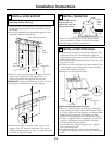
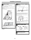
• Drive mounting screws into the studs until they
protrude ¼”. This ¼” gap will provide clearance to
engage the keyhole slots in the top of the hood.
• Lift hood onto mounting screws. Slide back against
the rear wall.
• Pull house wiring through the knockout at the rear or
the top of the hood.
• Tighten mounting screws.
Transition
Cabinet or
Soffit
¼” Gap
Add Shims
If Bottom Is
Recessed
Back Wall
Engage Keyhole
Slots and Push
Back to Wall