


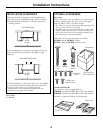
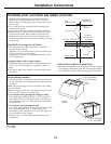
Ductwork Planning
• This hood may be vented vertically through upper
cabinets, soffit or ceiling. A duct transition piece is
supplied for vertical exhaust. Use locally supplied
elbows to vent horizontally through the rear wall.
See page 13.
• Determine the exact location of the vent hood.
• Use the shortest and straightest duct route possible.
For satisfactory performance, duct run should not
exceed 100 equivalent length for any duct
configurations.
• Refer to “Duct Fittings” chart to compute the
maximum permissible length for duct runs to the
outdoors.
• Use metal ductwork only.
• A transition piece for 7” round duct is supplied. Use 7”
round duct or you may use 3¼” x 12” rectangular.
• Install a wall cap or roof cap with damper at the
exterior opening. Order the wall or roof cap and any
transition needed in advance.
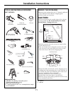
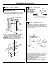
Kit - JXDW1
Order kit JXDW1 if your installation requires horizontal
ducting from the top of the hood through the back wall
and:
• You have an 8 ft. ceiling and need to use a JXCH
Series Chimney Cover, or
• You have a 12” cabinet or 12” soffit that the hood is to
be mounted beneath.
This kit provides a duct transition from 7” round to
3¼” x 10” rectangular for through-the-wall venting.
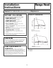
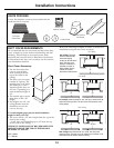
Wall Framing for Adequate Support
• This vent hood is heavy. Adequate structural support
must be provided. The hood must be secured to
vertical studs in the wall. See page 14.
• We strongly recommend that the vent hood with duct
cover be on site before final framing and wall
finishing. This will also help to accurately locate the
ductwork and electrical service.
ADVANCE PLANNING
Installation Instructions
1 Ft = 0.3 m
1” = 2.5 cm
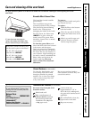
DECORATIVE DUCT COVERS
A decorative duct cover is available to fit both model
widths. The duct cover conceals the ductwork running
from the top of the hood to the ceiling or soffit. The
duct cover will fit 8 ft. to 10 ft. ceiling heights. See page
12 for details.
9
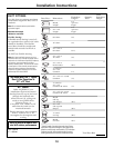
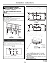
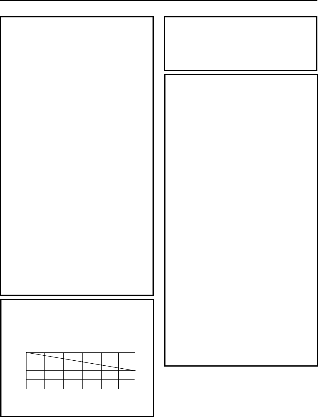
Follow these guidelines for proper duct sizing in the
ducting charts.
DUCT FITTINGS
MAXIMUM DUCT LENGTH: 7” dia. duct, should not
exceed 100 equivalent feet.
025
50
75 100 125 150
600
500
400
300
200
Equivalent Length in Feet for 7” Round Duct
Air Volume in CFM
7” Round 90° Elbow = 8 ft.
7” Roof Cap = 30 ft.
DUCTING CHART - 30” and 36” Models
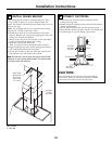
POWER SUPPLY
IMPORTANT - (Please read carefully)
WARNING:
FOR PERSONAL SAFETY, THIS APPLIANCE MUST BE
PROPERLY GROUNDED.
Remove house fuse or open circuit breaker before
beginning installation.
Do not use an extension cord or adapter plug with this
appliance. Follow National electrical codes or prevailing
local codes and ordinances.
Electrical supply
This vent hood must be supplied with 120V, 60Hz, and
connected to an individual, properly grounded branch
circuit, and protected by a 15 or 20 amp circuit breaker
or time delay fuse.
• Wiring must be 2 wire with ground.
• If the electrical supply does not meet the above
requirements, call a licensed electrician before
proceeding.
• Route house wiring as close to the installation location
as possible in the ceiling, soffit or wall. See page 13 for
details.
• Connect the wiring to the house wiring in accordance
with local codes.
Grounding instructions
The grounding conductor must be connected to a
ground metal, permanent wiring system, or an
equipment-grounding terminal or lead on the hood.
WARNING:
The improper connection of the equipment-grounding
conductor can result in a risk of electric shock. Check
with a qualified electrician or service representative if
you are in doubt whether the appliance is properly
grounded.