


11
®
The energy recovery wheel operation can be altered to take advantage of economizer operation (free cooling).
Two modes are available: 1) De-energizing the wheel or 2) Modulating the wheel.
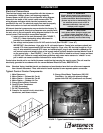
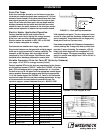
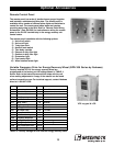
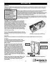
De-energizing the wheel is accomplished with a signal from a Temperature or Enthalpy sensor mounted in
the supply air inlet compartment (see FIGURE 15). This Primary sensor will de-energize the energy wheel when
the outdoor air temperature (factory default is 65°F) or enthalpy (factory default is the ‘D’ setting) is below the
field adjustable set point. An Override temperature sensor is also furnished in the supply air inlet compartment
to deactivate economizer mode (see FIGURE 15). The Override (with field adjustable set point) is set at some
temperature lower than the Primary sensor (factory default is 50°F). Effectively, the two sensors create a
deadband where the energy recovery wheel will not operate and free cooling from outside can be brought into
the building unconditioned.
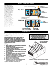
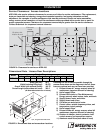
Testing (terminals referenced below are in the unit control center — see FIGURE 7, Item #7)
Temperature sensor with Override
• Turn both Temperature and Override thermostats down
as low as they go. The wheel should be rotating.
• Turn the Temperature sensor up as high as it goes, and
keep the Override sensor as low as it will go. The wheel
should stop rotating.
• Turn both sensors as high as they will go. The wheel
should start rotating.
• Set the Temperature sensor at desired point for
economizer operation to begin. Set the Override sensor
at desired point for economizer operation to end
(factory default is 65°F and 50°F, respectively).
Enthalpy sensor with Override
• A factory-installed 620 ohm resistor is connected across terminals SR and +. The Override sensor
should be turned down below current temperature in unit. Turn the unit on; LED on the sensor should
be off. Confirm continuity across terminals 1 and 2 and no continuity across terminals 2 and 3.
• Disconnect the 620 ohm resistor from terminals SR and +. LED should turn on. Confirm continuity
across terminals 2 and 3 and no continuity across terminals 1 and 2.
• Turn Override sensor above current temperature in unit. Confirm continuity across terminals 3 and 6.
Set the Override sensor to the desired point for economizer operation to end (factory default is 50°F).
• Reconnect the factory-installed jumper.
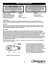
Modulating the Wheel
In applications in which an internal heat gain is present in the space, the rotational speed of the energy wheel
may be modulated (via variable frequency drive) to avoid overheating the space during the winter. The speed of
the energy wheel will be controlled in response to the discharge temperature set point.
Sequence of Operation: The variable frequency drive is fully programmed at the factory. A ‘call for cool’ must
be field wired to the unit (terminals provided in unit - refer to wiring diagram in unit control center) to allow for
initiation of economizer mode. When the space calls for cooling, factory supplied controls will drive the
following wheel operations:
T
OA
> T
RA
: Wheel runs at full speed (maximum energy recovery)
T
OA
< T
RA
and T
OA
> T
SA
: Wheel is stopped (no energy recovery)
T
OA
< T
RA
and T
OA
< T
SA
: Wheel will modulate to maintain discharge temperature
where (T
OA
) is the outdoor air temperature set point, (T
RA
) is the return air temperature set point, and (T
SA
) is the
supply air discharge thermostat set point (nominal 60°F – not adjustable).
Economizer Application/Operation
Enthalpy Sensor
(Primary Sensor)
Timed Exhaust
Frost Control
Override
Probes
FIGURE 15
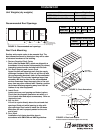
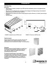
Installation