


16
®
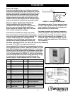
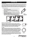
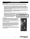
WRONG WRONG
WRONG CORRECT
Belt Drive Installation
1. Remove the protective coating from the end of the fan shaft and ensure
that it is free of nicks and burrs.
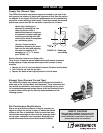
2. Check fan and motor shafts for parallel and angular alignment.
3. Slide sheaves on shafts - do not drive sheaves on as this may result in
bearing damage.
4. Align fan and motor sheaves with a straight-edge or string and tighten.
5. Place belts over sheaves. Do not pry or force belts, as this could result in
damage to the cords in the belts.
6. With the fan off, adjust the belt tension by moving the motor base. (See
belt tensioning procedures in the Routine Maintenance section of this
manual). When in operation, the tight side of the belts should be in a
straight line from sheave to sheave with a slight bow on the slack side.
Fan Belt Drives
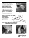
The fan belt drive components, when supplied by Greenheck Fan Corporation, have been carefully selected for
the unit's specific operating condition. Caution: utilizing different components than those supplied could result in
unsafe operating conditions which may cause personal injury or failure of the following components: 1) Fan
Shaft, 2) Fan Wheel, 3) Bearings, 4) Belt, 5) Motor. Tighten all fasteners and set screws securely and realign drive
pulleys after adjustment. Check pulleys and belts for proper alignment to avoid unnecessary belt wear, noise,
vibration and power loss. Motor and drive shafts must be parallel and pulleys in line (see FIGURES 17 & 18).
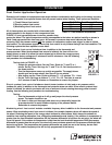
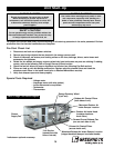
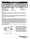
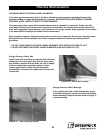
Direction of Fan Wheel Rotation
Blower access is labeled on unit. Check for proper wheel rotation by momentarily
energizing the fan. Rotation is determined by viewing the wheel from the drive side and
should match the rotation decal affixed to the fan housing (see FIGURE 19). If the wheel
is rotating the wrong way, direction can be reversed by interchanging any two of the
three electrical leads.
Check for unusual noise, vibration, or overheating of bearings.
Refer to the “Troubleshooting” section of this manual if a problem develops.
Fan RPM
Supply fan will have a fixed motor pulley. Exhaust fans will have an adjustable motor
pulley (on 15 HP and below) preset at the factory to the customer specified RPM. Fan
speed can be increased or decreased by adjusting the pitch diameter of the motor pulley.
Multi-groove variable pitch pulleys must be adjusted an equal number of turns open or
closed. For the exhaust blowers, any increase in fan speed represents a substantial
increase in load on the motor. Always check the motor amperage reading and compare it
to the amperage rating shown on the motor nameplate when changing fan RPM.
For Exhaust Fans. All access doors must be installed except the control center door.
Close off as much of the exhaust blower access opening as possible while measuring the
amp draw. Do not operate units with access doors open or without proper ductwork in
place as the exhaust motors will overload.
R
o
t
a
t
i
o
n
Airflow
FIGURE 19
R
o
t
a
t
i
o
n
Unit Start-Up
FIGURE 17: Aligning
sheaves with a
straight edge
FIGURE 18: Proper alignment of motor and drive shaft.