


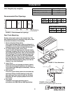
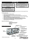

Drain Pan Traps
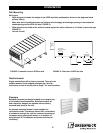
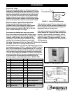
Drain lines and traps should be run full size or larger from
the drain pan connection (drain pan connection is 1.25-inch
diameter female thread). Drain pans should have drain lines
and traps to permit the condensate from the coils to drain
freely. On all units with drain pans, the trap depth and the
distance between the trap outlet and the drain pan outlet
should be twice the static pressure in the drain pan section
under normal operation to assure the trap remains sealed.
6 in. min.
6 in. min.
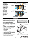
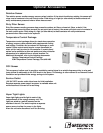
Electric Heater Application/Operation
9
®
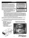
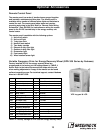
Factory installed electric post-heaters can be
provided to warm the air leaving the energy recovery
wheel to a user specified discharge temperature.
Electric heaters are available in 208, 230, or 460 VAC
(refer to heater nameplate for voltage).
Post-heaters are standard as 4-stage, step control.
Step control heaters are designed with multiple stages
made up of equal increments of heating capability. For
example, an 80 kW heater with four stages will be
composed of four 20-kW stages. Post-heaters come
standard with a discharge temperature sensor (with
field adjustable set point). The four stages will come
on one at a time until the discharge temperature set
point is satisfied). Post-heaters are not single point
wired (see Electrical Connections).
Post-heaters supplied with Greenheck temperature
control package are 3-stage with binary control that
provides 7 steps of heating. For example, a 35 kW
heater with three stages will be composed of 5, 10,
and 20 kW stages. The stages essentially ‘mix and
match’ to provide heat output from 5 kW to 35 kW, in
5 kW increments.
FIGURE 11: Drain pan trap dimensions.
Installation
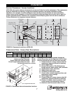
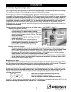
Variable Frequency Drive for Fans (E7 Series by Yaskawa)
(see page 13 for VFD on energy recovery wheel)
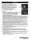
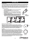
Factory installed VFDs for the fans are programmed at the factory
per the settings shown in TABLE 1 below (see FIGURE 12 for key
pad). VFDs are shipped with a jumper between A1 to +V to allow
the unit to turn on at full speed until the appropriate control signal
can be applied. Remove the jumper when wiring the appropriate
.0-10 Vdc control signal. See FIGURE 13. Refer to the instruction
manual that ships with the unit when making adjustments. A copy
of the manual can be found online at www.drives.com. For
technical support, contact Yaskawa direct at 1-800-927-5292.
TABLE 1: Factory settings for VFD used on fans
FIGURE 13: Control signal to VFD
FIGURE 12: VFD key pad & LCD
Parameters Setting Comment
A1-01 Access Level 2 Advanced Level
A1-04 Password 0 Leave as default
b1-01 (Frequency) Ref Source 1 Terminal - Analog Input A1
b1-02 Run (Command) Source 1 Contact Closure on S1
C1-01 Accl Time 1 30 Seconds
C1-02 Decel Time 2 30 Seconds
d2-01 Ref Upper Limit 100% % of E1-04
d2-02 Ref Lower Limit 50% % of E1-04
E1-04 Max Frequency 60 Hz Ref for d2-01, d2-02, H3-03
E2-01 Motor Rated FLA ? A Nameplate amps
H3-02 Terminal A1 Gain 100% 10V = 60 Hz, 100% of E1-04
H3-03 Terminal A1 Bias 50% 0V = 30 Hz, 50% of E1-04
L8-10 Cooling Fan Operation 0 Fan only during RUN
O2-03 User Defaults 1 Saves setting as user defaults
Set defaults by A1-03 = 1110
A1-01 Access Level 0 Operation Only