


Water Coils
1. Piping should be in accordance with accepted industry standards.
Pipework should be supported independently of the coils. Water
connections are male N.P.T iron pipe. When installing couplings,
do not apply undue stress to the connection extending through
the unit. Use a backup pipe wrench to avoid breaking the weld
between coil connection and header.
2. Connect the WATER SUPPLY TO THE BOTTOM CONNECTION on the air leaving side and the WATER
RETURN TO THE TOP CONNECTION on the air entering side. To ensure proper venting, an external air vent
in the piping is recommended. Connecting the supply and/or return in any other manner will result in very
poor performance. Be sure to replace factory installed grommets around coil connections if removed for
piping. Failure to replace grommets will result in water leakage into the unit and altered performance.
3. The air vent at the uppermost point should be temporarily opened during system start-up to release all of
the air from the coil. To maintain heat transfer capacity, periodically vent any air in coil.
4. Water coils are not normally recommended for use with entering air temperatures below 40
o
F; however, the
energy recovery wheel maintains a pre-coil temperature higher than 40
o
F. No control system can be
depended on to be 100% safe against freeze-up with water coils. Glycol solutions or brines are the only
safe media for operation of water coils with low entering air temperatures.
CONTINUOUS WATER CIRCULATION THROUGH THE COIL AT ALL TIMES IS HIGHLY RECOMMENDED.
5. Pipe sizes for the system must be selected on the basis of the head (pressure) available from the circulation
pump. The velocity should not exceed 6 feet per second and the friction loss should be approximately
3 feet of water column per 100 feet of pipe.
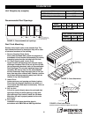
6. For chilled water coils, the condensate drain pipe should be sized adequately to ensure the condensate
drains properly. See Drain Pan Traps and FIGURE 11.
Direct Expansion (DX) Coils
1. Piping should be in accordance with accepted industry standards. Pipework should be supported
independently of the coils. Undue stress should not be applied at the connection to coil headers.
2. The condensate drain pipe should be sized adequately to ensure the condensate drains properly. See Drain
Pan Traps and FIGURE 11.
3. When connecting suction and liquid connections make sure the coil is free from all foreign material. Make
sure all joints are tight and free of leakage. Be sure to replace factory installed grommets around coil
connections if removed for piping.
4. Greenheck does not supply condensing units; for further instruction on DX coil installation and operation
contact your condensing unit manufacturer.
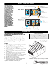
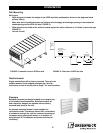
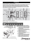
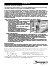
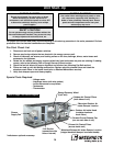
Coil Application Recommendations
Factory installed cooling and heating components are mounted
in the coil section of the unit. The coil section is downstream of
the energy wheel on the supply air side of the unit.
See FIGURE 10 for coil connection location. Coil connections
are located external to the unit as shown. Coil connections that
are not external have been ordered from the factory with
interior or exhaust airstream coil connections.
Note: DX coil liquid connections are accessible through
access doors shown in FIGURE 10.
FIGURE 10
8
®
Water coil
connections
Installation
Water coil
connections
DX coil liquid
connection
access door