


14
®
For proper unit function and safety, follow everything in this start-up procedure in the order presented. Perform
procedure after the electrical connections are complete.
Pre-Start Check List
1. Disconnect and lock-out all power switches.
2. Remove any foreign objects that are located in the energy recovery unit.
3. Check all fasteners, set screws, and locking collars on the fans, bearings, drives, motor bases and
accessories for tightness.
4. Rotate the fan wheels and energy recovery wheels by hand and ensure no parts are rubbing. If rubbing
occurs, refer to the following Fan or Energy Recovery Wheel section.
5. Check the fan belt drives for proper alignment and tension (see following Fan Belt section).
6. Filters can load up with dirt during construction. Replace any dirty pleated filters and clean the
aluminum mesh filters in the intake hood (refer to Routine Maintenance section).
7. Verify that dampers open and close properly.
Special Tools Required
• Voltage meter
• Amperage meter (with wire probes)
• Incline manometer or equivalent
• Tachometer
• Thermometer
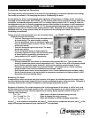
SAFETY CAUTION!
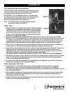
Use caution when removing access panels or other
unit components, especially while standing on a
ladder or other potentially unsteady base. Access
panels and unit components can be heavy and
serious injury may occur.
SAFETY CAUTION!
Do not operate energy recovery ventilator without the
filters and birdscreens installed. They prevent the entry
of foreign objects such as leaves, birds, etc.
SAFETY DANGER!
Electric shock hazard. Can cause injury or death.
Before attempting to perform any service or
maintenance, turn the electrical power to unit to OFF
at disconnect switch(es). Unit may have multiple
power supplies.
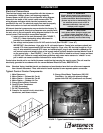
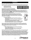
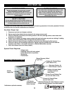
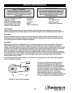
Plenum
Supply Fan
Forward Curved Exhaust Fan
(one on each side of unit)
Energy Recovery Wheel
(2 per unit)
*Coil Section
(connections this
side or internal)
Outdoor Air Intake Hood
(contains aluminum
mesh filters)
Outdoor Air Pleated Filters
(both sides of unit)
Exhaust Air Pleated Filters
(access inside unit)
Refer to Page 3 for Airflow Diagram
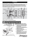
Unit Start-Up
*Motorized Outdoor Air
Intake Damper Location
*Motorized Exhaust Air Intake Damper Location
(integral backdraft damper in exhaust hoods)
*Indicates an optional accessory.