


– 11 –
To Reinstall the Knife . . .
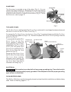
• Orient the RIDGE on the KNIFE HUB so it points to the PIN on
the RING GUARD at the 1 o'clock position (Fig. 24).
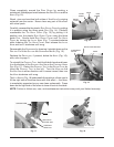
• Place the K
NIFE and TOOL so the PIN on the KNIFE REMOVAL
TOOL is at the 11 o'clock position (Fig. 23). The SLOTS on
the K
NIFE REMOVAL TOOL fit around the three PINS on the
R
ING GUARD (FIG. 20).
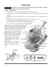
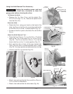
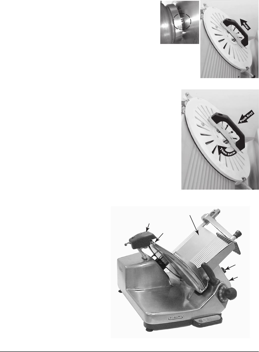
• If the T
OOL does not push the pins on the back of the KNIFE
into the HUB (Fig. 25), slightly nudge the HANDLE upwards
(Fig. 26) to lock the pins into the K
NIFE NUT.
• First, push the H
ANDLE firmly, all the way into the HUB to engage
the pins. Then, turn the H
ANDLE clockwise until it stops (Fig. 27).
You may experience resistance when turning.
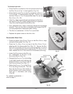
• The K
NIFE is reattached. Lift the TOOL up and out.
• Replace the plastic cover on the K
NIFE NUT.
Reassemble Slicer Parts
• Place the plastic R
ING GUARD COVER on the RING GUARD, align
using the three guide P
INS (Fig. 14).
• Place the T
OP KNIFE COVER on top of the RING GUARD COVER,
aligning with the three guide P
INS (Fig. 13). Secure the RING
GUARD COVER and the TOP KNIFE COVER by turning the LATCH KNOB
(Fig. 7) counterclockwise while lowering the TOP KNIFE COVER;
then, release the L
ATCH KNOB and turn it clockwise until snug.
• Lower the S
HARPENER so the ROD AND
PIN, underneath, fit the SLOT in the
S
HARPENER MOUNT (Fig. 12).
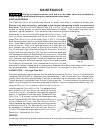
• Reinstall the P
RODUCT TRAY by holding
it with both hands and lowering the
bottom of the S
UPPORT ARM so it fits on
the C
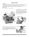
ARRIAGE HINGE PINS (Fig. 17).
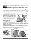
• Return the P
RODUCT TRAY to the GAUGE
PLATE by tilting it to the left. Turn the
K
NOB on the SUPPORT ARM loosely in
either direction until it moves inward,
then turn it clockwise until snug
(Fig. 28).
To reattach accessories —
refer to page 3.
SHARPENER
KNIFE COVER
KNOB
PRODUCT TRAY
SUPPORT
ARM
Fig. 28
Fig. 26
Fig. 25
Fig. 27