


33
SERVICING
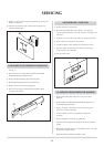
a) Remove the upper programmer retaining panel, four screw and
starlock washers at the four corners of panel.
b) Supporting the panel ease forward and release 6 way plug
(two lugs). Carefully put panel at one side.
c) Access to the underside of the control panel will need to be
gained by following the section above. Unclip the 7 way plug
from the control panel.
d) The 3 thermostats phials for the boiler thermostats are all located
above the boiler inspection cover. Remove the 3 split pins and
retain, carefully remove from the pockets.
e) Remove the control panel from the unit (4 screws and starlock
washers) and support, as the two cooker thermostats will be still
in position.
f) Remove the heat shield from the control panel, (two brown
screws). Identify and remove faulty thermostat. Removing knob
if appropriate and retaining screws.
a) Remove the upper programmer retaining panel, four screw and
starlock washers at four corners of panel.
b) Supporting the panel ease froward and release 6 way plug (two
lugs) carefully put panel to one side.
c) Access to the underside of the control panel will need to be
gained by following the section above, unclip the 7 way plug
from the control panel.
d) Remove the heat shield from behind the control panel
(two brown screws from front).
e) The two cooker control thermostats are located in the top oven,
the control thermostat phial located at the bottom RHS of the
oven, the limit thermostat phial on the top LHS of the oven.
f) Control thermostat
• Remove the infill panel at the bottom front of the oven,
remove the phial from the phial clip and pull phial through
insulation at side of oven.
• Remove control knob and thermostat two screws from front.
• Replace in reverse order ensure that the phial is in correct
position and capillary not kinked.
g) Cooker limit thermostat.
• Remove the limit phial securing bracket two screws.
• Pull phial through insulation at side of oven.
•Remove the knob and the two thermostat front retaining
screws.
• Replace in reverse order ensuring that phial is in correct
position and capillary not kinked.
a) Remove the upper programmer retaining panel, four screw and
starlock washers at four corners of panel.
b) Supporting panel ease forward and release 6 way plug
(two lugs)
c) Remove rear heat shield, 4 outer screws on programmer
mounting panel
d) Remove the smaller inner counter sunk screws and release
programmer.
e) Remove electrical connections and set up programmer as
required.
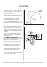
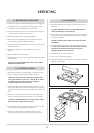
5. BOILER THERMOSTATS
7. COOKER PROGRAMMER
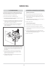
6. COOKER THERMOSTATS
BOILER CONTROL
BOILER LIMIT
PUMP OVERRUN
COOKER LIMIT
COOKER CONTROL
INFILL PANEL