


11
2. Diagnostic Procedure
The diagnostic procedure is a sequence check that allows you to diagnose the electrical
system and components. Before proceeding, check for correct installation, adequate
water pressure (10 to 113 PSIG), and proper voltage per unit nameplate.
Note: • When checking high voltage (115VAC), always choose a neutral (W) wire to
establish a good neutral connection.
• When checking low voltage (24VAC), always choose a neutral (LBU) wire.
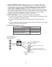
• When checking control board DC voltage (5VDC), always place the red positive
test lead from the multimeter to CB K5 pin closest to CB K4 connector.
See "II.C. Control Board Check."
• To speed up the diagnostic process, the 5-min. ice purge cycle may be bypassed
by pressing the "SERVICE" button on the control board after the gear motor
starts. WARNING! Risk of electric shock. Care should be taken not to touch
live terminals.
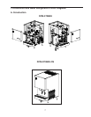
1) Move the power switch to the "OFF" position, then disconnect the power cord from the
electrical outlet. Remove the front, top, and left side panels. Remove the control box
cover.
2) Reconnect the power cord into the electrical outlet, then move the power switch to the
"ON" position.
3) Move the control switch to the "DRAIN" position. CB "POWER OK" LED and "FLUSH"
(drain) LED turns on.
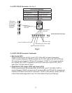
Diagnosis "POWER OK" LED: Check that CB "POWER OK" LED is on. If not, check
for 115VAC at control transformer brown (BR) wire to neutral (W). If 115VAC is not
present, check the power switch, power cord connection, and breaker. If 115VAC is
present, check control transformer continuity. Replace as needed. Next, check for
24VAC at control transformer red (R) wire to neutral (LBU). If 24VAC is not present,
check control transformer continuity. Replace as needed. If 24VAC is present, check
24VAC 1A fuse. If fuse is good, check for 24VAC at CB K8 #1 (W/R) to CB K8 #2 (LBU).
If 24VAC is present and "POWER OK" LED is off, replace CB.
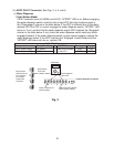
Diagnosis DV: If DV does not energize, check for 24VAC at CB K2 #10 (W/DBU) to
neutral (LBU). If24VAC is not present, check control switch continuity. If open while in
the "DRAIN" position, replace control switch. If closed, check for 0VDC at control board
K9 #1 (W/BK) to K9 #2 (W/BK). If5VDC is present and control switch is closed, replace
CB. If 24VAC is present, check for restricted DV and DV solenoid continuity. Clean or
replace as needed.
3) After all of the water has drained, move control switch to the "ICE" position.