12
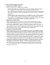
4) Fill Cycle – "WTRIN" LED is on. WV energizes. The 90-sec. low water safety timer
begins. LFS closes. Nothing occurs at this time. The reservoir continues to ll until
UFS closes, terminating the 90-sec. low water safety timer, starting the 30-min. freeze
timer, and de-energizing WV. Diagnosis: Check that "WTRIN" LED turns on and water
lls the reservoir. If not, check for water supply line shut-off valve closed, restricted
water lters, and restricted WV screen. Next, check for 24VAC at CB K2 #8 (W/BR)
to neutral(LBU). If 24VAC is not present, replace CB. If 24VAC is present, turn off the
power switch, disconnect the WV wires and check WV solenoid continuity. If open,
replace WV. Reconnect WV wires, move the power switch to the "ON" position, then
check that DV is not leaking by. Check that WV shuts off when UFS closes.
Note: Low Water Safety– If UFS remains open 90 sec. after WV energizes, a 1-beep
alarm sounds. This alarm resets automatically once UFS closes.
5) Ice Purge Cycle – "GM" LED is on. 5-sec. GM delay timer and 30-min. freeze timer
start. WV de-energizes and "WTRIN" LED turns off. Once the 5-sec. GM delay timer
terminates, GM and CDR energize. CDR cannot energize unless GM circuit is complete
(fuse, internal protector, and windings). Once CDR energizes, CB K9 #5 W/O and
CB K9 #6 W/O 5VDC circuit closes and 5-min. ice purge timer starts. See "II.C.3)c.
Compressor Delay Relay (5-min. Ice Purge Timer Circuit)." If CDR de-energizes, CB
K9#5 W/O and CB K9 #6 W/O circuit opens and an 8-beep alarm occurs. See "III.B.
LED Lights and Alarm Safeties." Note: To bypass ice purge cycle and go straight to
freeze cycle, press "SERVICE" button on CB during 5-sec. GM delay time.
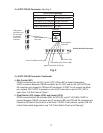
Diagnosis CB: Check that UFS closed, WV LED turned off and WVde-energized.
IfUFS is closed, "WV" LED is off, and "GM" LED is off, replace CB. If "GM" LED is
on and GM is off, conrm 115VAC at CB K1 #2 (BR) to neutral(W). If115VAC is not
present, check for loose connection from power switch. If 115VAC is present, check for
115VAC at CB K1 #3 (BK) to neutral (W). If115VAC is not present, replace CB.
Diagnosis GM: If115VAC is present at CB K1 #2 (BR) to neutral(W), check GM fuse,
GM capacitor, GM windings, and GM coupling between auger and GM.
Diagnosis CDR: See "II.C.3)c. Compressor Delay Relay (5-min. Ice Purge Timer
Circuit)." Once 5-min. ice purge timer terminates, freeze cycle begins.
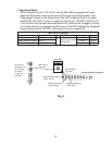
6) Freeze Cycle – "COMP" LED is on. 5-min. ice purge timer terminates or "SERVICE"
button pressed. "COMP" LED turns on. "GM" LED remains on. Comp and FM energize.
GM and CDR continue. Ice production begins 4 to 6 minutes after Comp energizes
depending on ambient and water conditions. Diagnosis Comp: Check that "COMP"
LED is on and that Comp energizes. If "COMP" LED is off, conrm 5-min. ice purge
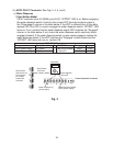
timer has terminated. Check for 0VDC across CB K9 #3 (W/O) and CB K9 #5 (W/O).
If 5VDC is present, CDR contacts are open. Check for 115VAC at CDR #7 (O) to CDR
#8 (W). If115VAC is present, check CDR continuity between CDR #3 (W/O) and
CDR #5 (W/O). If open, replace CDR. If closed and"COMP" LED remains off, replace
CB. If"COMP" LED is on and Comp is off, check for 115VAC at each CB X1 brown
(BR) wire to neutral(W). If 115VAC is present on one and not the other, replace CB.
If115VAC is present on both, check Comp windings, start relay, and capacitors.
Note: If CDR de-energizes, CB K9 #5 W/O and CB K9 #6 W/O circuit opens, Comp
de-energizes and an 8-beep alarm occurs. See "III.B. LED Lights and Alarm Safeties."
Diagnosis FM: If FM does not energize, check FM capacitor, windings, and bearings.


