


15
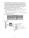
1) Startup-"POWER OK" LED on: Move control switch to "ICE" position, then move
power switch to "ON" position. "POWER OK" LED turns on. "POWER" LED remains
on unless power supply is interrupted. NOTICE!Appliance will not start unless the
safety switch is engaged. Diagnosis: Checkthat "POWER OK" LED is on. If not,
check for proper 115VAC supply voltage to CT (main breaker or fuse and power switch).
Next, check for proper 24VAC output from CT. Next, check that 1A fuse is good. Check
for 24VAC from CB K8connector pin #1 (W/R) to CB K8 connector pin #2(LBU).
If24VAC is present and "POWER OK" LED is off, replace CB.
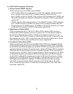
2) 5VDC Output Checks: There are seven 5VDC circuits on the appliance.
a) 3 circuits at CB K9 connector: Control switch "DRAIN" position, high-pressure switch
(HPS), and compressor delay relay (CDR).
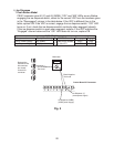
b) 2 circuits at CB K8 connector: Bincontrol (BC) and oat switch (FS upper and
lower).
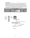
c) 2 circuits at CB K7 connector: Ice dispense (push button, and OS sensor), and water
dispense (push button and OS sensor).
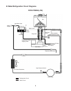
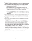
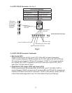
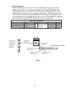
2a) 5VDC CB K9 Connector: See Fig. 1.
5VDC CB K9 Connector
Component Pin # (Wire Color)
Control Switch "DRAIN" Position #1 (W/BK) and #2 (W/BK)
High-Pressure Switch (HPS) #3 (Y) and #4 (Y)
Compressor Delay Relay (CDR)
(CDR relay terminals #3 W/O and #5 W/O)
#5 (W/O) and #6 (W/O)
Red positive test lead to
redK4 connector pin closest
to black K3 connector
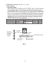
Fig. 1
Control Board K9 Connector
Red Positive
Test Lead
Black Negative
Test Lead
Multimeter
5VDC
"DRAIN" Position on
Control Switch
(W/BK)
High-Pressure Switch (HPS) (Y)
Compressor Delay Relay (CDR)
CDR Terminals #3 (W/O) and #5 (W/O)