


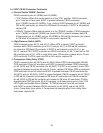
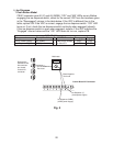
16
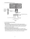
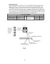
2a) 5VDC CB K9 Connector Continued:
a) Control Switch"DRAIN" Position
CB K9 connector pins #1 (W/BK) and #2 (W/BK):
• "ICE" Position: When the control switch is in the "ICE" position, CB K9 connector
pin#1and pin #2are open. 5VDC is present between CB K9 connector
pin #1(W/BK) and pin #2 (W/BK). If not, conrm 5VDC between pin#1 (W/BK) and
CBred K4 connector, pin closest to CBblack K3connector. If 5VDC is not present,
replace CB.
• "DRAIN" Position: When control switch is in the "DRAIN" position, CB K9 connector
pin #1 (W/BK) and pin#2(W/BK) are closed. 5VDC is present between both CB
K9connector pin #1(W/BK) and pin#2 (W/BK) to CBred K4connector, pin closest
to CB black K3 connector. If 5VDC is not present, replace CB.
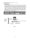
b) High-Pressure Switch (HPS)
CB K9 connector pins #3 (Y) and #4 (Y): When HPS is closed, 5VDC is present
between both CB K9 connector pins #3(Y) and pin #4 (Y) to CB red K4 connector
pin closest to CB black K3 connector. If5VDC is not present on pin #3 (Y) or pin
#4(Y), replace CB. If 5VDC is present on CBK9connector pin #3 (Y) and not on CB
K9connector pin #4 (Y), HPS is most likely open. CB sounds a 3-beep alarm. Check
HPS continuity. If HPS is open and CB is not in alarm, replace CB.
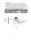
c) Compressor Delay Relay (CDR)
CB K9 connector pins #5 (W/O) and #6(W/O): When CDR is de-energized (GM off),
CDRterminals #3 and #5 are open and 5VDC is present between CBK9connector
pin #5 (W/O) and CBK9connector pin #6(W/O). If5VDC is not present, check CDR
continuity between terminals #3 and #5. If open, replaceCB. When CDR is energized,
CDR terminals #3 and #5close and 0VDC is present between CB K9 connector pin
#5 (W/O) and pin #6(W/O). 5VDC is present between CB K9 connector pin #5 (W/O)
to CB red K4 connector pin closest to CB black K3connector and CB K9 connector
pin #6 (W/O) to CB red K4 connector pin closest to CB black K3connector. If GM is
energized and CDR terminals #3& #5 are open, an 8-beep alarm occurs. See "III.B.
LED Lights and Audible Alarm Safeties." If CDR terminals #3 and #5 are closed
and 0VDC is present between CB K9 connector pin #5 (W/O) and pin #6(W/O),
5-min. Comp delay timer starts. IfComp does not energize after 5-min. delay timer
terminates, replace CB.