


15
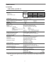
• Minimum freeze time: 5 min.
• Maximum freeze time: freeze timer setting
(S4 dip switch 9 & 10).
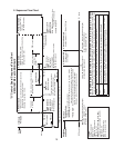
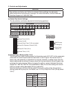
2. Sequence Flow Chart
Components Energized when the Control Switch is in the "SERVICE" Position
When in the "SERVICE" position, the control switch supplies power to the service switch and the icemaker is in service mode.
The service switch has three positions: "DRAIN," "CIRC." and "WASH." See the information below for details of each function.
DRAIN
Power is supplied to the pump and drain valve. This drains the water tank.
CIRC.
Power is supplied to the pump only. This operation can be used to circulate cleaner and
sanitizer over the outside surface of the evaporator for extended periods of time.
WASH
Power is supplied to the pump and wash valve. This operation is used to circulate cleaner
and sanitizer over both the inside and outside surfaces of the evaporator.
4. Pump-Out Cycle
1. 1-Minute
Fill Cycle
2. Harvest Cycle
3. Freeze Cycle
Cycle
Steps
WV1 energized
F/S open
F/S closed
Comp energized
FMRs energized
HGVs energized
WV2 energized
WV1 de-energized
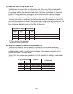
Thermistor temperature reaches
48°F (9°C) (3.9 kΩ or less).
Harvest timer starts (1 to 3 min.).
F/S open
Comp continues
FMRs continue
PM continues
LLVs energized
WV1 energized rst 1 min. of freeze
HGVs de-energized
F/S closed
Comp continues
FMRs continue
HGVs energized
DV & PM de-energized 2 sec., then
energized for 10/20sec.
LLVs de-energized
F/S check
F/S check
• WV2 time: 6 min. or the length of harvest minus 50 sec.
(S4 dip switch 7), whichever is shorter.
• Maximum harvest time: 20 min.
Thermistor
in control
1 to 3-min. harvest timer in control
(S4 dip switch 1 & 2)
5-min. minimum
freeze timer in
control
F/S in control
Startup
If F/S is open, Comp stops and cycle returns to 1-min. ll.
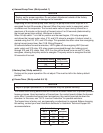
Factory set forevery
10th cycle.
(S4 dip switch 5 & 6)
50 sec.
PM energized
WV2 de-energized
HarvestPump
Timer
F/S opens or freeze
timer terminates
1. Bin Full
Shutdown Delay:
• Fill Cycle – 15 sec. after activation.
• Harvest Cycle – At the end of the harvest cycle, or up to 15 sec. into the
freeze cycle if activated at the end of the harvest cycle.
• Freeze Cycle – 15 sec. after activation if activated at least 15 sec. before
the 5-min. short cycle protection timer terminates.
Otherwise, at the end of the next harvest cycle.
Shutdown
andRestart
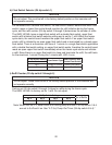
BC Operation
BC open (BC actuator paddle engaged)
Green "BC CLOSED" LED off
Yellow "BC OPEN" LED on
Yellow "BC OPEN" LED continues
All components de-energized
2. Icemaker Off
All components
de-energized.
3. Ice Level Lowered
Icemaker starts at "1. 1-Minute Fill Cycle."
To 1 above
BC closed (BC actuator paddle disengaged)
Green "BC CLOSED" LED on
Yellow "BC OPEN" LED off
Legend:
Comp-compressor
DV-drain valve
FMRs-fan motors-remote
F/S-oat switch
HGVs-hot gas valves (KMS and SRK)
LLVs-liquid line valves (KMS and SRK)
PM-pump motor
WV1-ll/rell water valve
WV2-harvest water valve
"G" Control Board Sequence Flow Chart
KMS-1401MLJ with SRK-14J/3
1 min.
Rell