


34
B. Control Board Check
Before replacing CB that does not show a visible defect and that you suspect is bad,
always conduct the following check procedure. This procedure will help you verify your
diagnosis.
Alarm Reset: If CB is in alarm (beeping), press the "ALARM RESET" button on CB
while CB is beeping. WARNING!Risk of electric shock. Care should be
taken not to touch live terminals. Once reset, the icemaker starts at the
1-minute ll cycle. For audible alarm information, see "II.C.2. LED Lights
and Audible Alarm Safeties."
1) Check the dip switch settings to assure that S4 dip switch 3, 4, 7, 8, 9, 10, and S5 dip
switch 1 through 5 are in the factory default position. S4 dip switch 1, 2, 5, 6 are
cleaning adjustments and the settings are exible. For factory default settings, see
"II.C.3.a) Default Dip Switch Settings."
2) Move the control switch to the "ICE" position. If the red "POWER OK" LED is on,
control voltage is good, continue to step 3. If the red "POWER OK" LED is off, check
CT secondary circuit. CT output is 10.5VAC at 115VAC primary input. If the secondary
circuit has proper voltage and the red LED is off, replace CB.
If the secondary circuit does not have proper voltage, check CT primary circuit. Check
for 115VAC at CB K1 connector pin #10 (BRwire) to a neutral (W wire) for 115VAC.
(Always choose a neutral (W wire) to establish a good neutral connection when
checking voltages.) For additional checks, see "IV.F.1. No Ice Production."
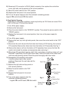
3) The "OUTPUT TEST" button provides a relay sequence test. Make sure the control
switch is in the "ICE" position, then press the "OUTPUT TEST" button. The correct
lighting sequence is 1, 4, 3, 2. Note that the order of the LEDs from the outer edge of
CB is 1, 4, 3, 2. Components (e.g., compressor) will cycle during the test. Following the
test, the icemaker begins operation at the 1-minute ll cycle. If the LEDs do not light as
described above, replace CB.
4) To verify voltage output from CB to the components, slide the CB K1 connector out far
enough to allow multimeter lead contact. With the icemaker in the cycle to be tested,
check output voltage from the corresponding pin on CB K1 connector to ground. If
output voltage is not found and the appropriate LED is on, replace CB.
Legend: CB–control board; CT–control transformer.