


17
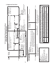
1. Control Board Layout
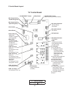
"G" Control Board
Part Number 2A3792-01
"G" Control Board
• Power LED (red)
(lights when
10.5VAC is supplied
to K2 connector)
• LED 3 (X3 Relay)
LED 3 on:
K1 Connector Pin #5
(energized during harvest
pump timer)
LED 3 off:
K1 Connector Pin #4
(energized in freeze)
• LED 4 (X4 Relay)
K1 Connector Pin #6
• LED 1 (X1 Relay)
K1 Connector Pin #1, #9
• K2 Connector
Control Transformer
(10.5VAC)
• S5 Dip Switch
• Bin Control Switch
Closed LED (green)
• "ALARM RESET" Button • S4 Dip Switch
• "OUTPUT TEST" Button
(used to test relays on control board)
• K3 (white) Connector
Harvest Control
(thermistor)
• K4 (red) Connector
Bin Control
• Label
(control board revision
level indicated on label
on side of relay)
• K5 (black) Connector
Float Switch
• Part Number
• Bin Control Switch
Open LED (yellow)
• Alarm Buzzer
• LED 2 (X2 Relay)
LED 2 on:
K1 Connector Pin #2
LED 2 off:
K1 Connector Pin #3
• Relay LEDs
(4) (indicate which
relays are energized
and which K1
connector pins are
energized
• K1 Connector
Pins #1 through #10
#1, 9 Magnetic Contactor,
X13 Relay (holding
circuit during Harvest
Pump Timer), and
Drain Valve (during
Pump-Out)
#2 Hot Gas Valves (KMS and
SRK) and X10 Relay
#3 Liquid Line Valves
#4 Pump Motor (freeze)
#5 X11 Relay (Pump Motor
in Harvest Pump Timer
and Drain Valve in
Pump-Out)
#6 Fill Water Valve (InitialFill
and Freeze Fill only);
Harvest WaterValve and
X12 Relay (Harvest only)
#7, 10 Supply Voltage
#8 Open