


33
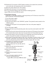
6) Pump-Out Cycle – LEDs 1, 3, and 2 are on (10/20 second pump-out) – The 1st
pump-out occurs after the 11th freeze cycle, then every 10th cycle thereafter. Comp
and FMRs remain energized. HGVs and X10 relay energize. LLVs de-energize.
PMde-energizes for 2 seconds, then X11 relay energizes, allowing PM and DV to
energize for 10seconds. PM energized through X11 relay (energized) terminal #4 (BR
wire) and terminal #6 (R wire), then through control switch terminal #6 (R wire) and
terminal #5(R wire). DV energized through X10 relay (energized) terminal #5 (V wire)
and terminal #3 (Y wire), then through X13 relay (de-energized) terminal #6 (Y wire)
and terminal #2 (LBU wire), then through X11 relay (energized) terminal #3 (LBU wire)
and terminal #5 (GY wire). This pump-out removes contaminants from the water tank
through DV and allows for a power ush of F/S. Diagnosis: PM Operation: If PM does
not come on, check CB K1 connector pin #5 (DBU wire) (X11 relay coil voltage) to a
neutral (W wire) for 115VAC. If LED 3 is on and 115VAC is not present, replace CB. If
115VAC is present, X11 relay should energize and X11 terminals #4 (BR wire) and #6
(R wire) should be closed. Check X11 relay terminal #6 (R wire) for 115VAC to a neutral
(W wire). If 115VAC is not present, check X11 relay coil and contact continuity. If 115VAC
is present and PM is still not energized, check control switch continuity between
terminal #5 (R wire) and #6 (R wire). If closed, check PM windings and capacitor. DV
Operation: If water does not pump out, check CB K1 connector pin #1 (V wire) (power
supply for DV operation) and CB K1 connector pin #2 (P wire) (X10 relay coil voltage
for DV operation) to a neutral (W wire) for 115VAC. If 115VAC is not present on either
circuit, replace CB. If 115VAC is present, X10 relay terminals #1 (Y wire) and #5 (V
wire) should be closed. Check X10 relay terminal #3 (Y wire) to a neutral (W wire) for
115VAC. If 115VAC is not present on terminal #3 (Y wire), check X10 relay coil and
contact continuity. If 115VAC is present on X10 relay terminal #3(Y wire), go to X13
relay and check X13relay terminal #2 (LBU wire) to a neutral (W wire) for 115VAC. If
115VAC is not present, check X13 relay contact continuity between terminal #2 (LBU
wire) and terminal #6 (Y wire). If contacts are open, conrm X13 is de-energized. If
115VAC is present, check X11 relay terminal #5 (GY wire) to a neutral (W wire) for
115VAC. If 115VAC is not present, check continuity between X11 relay (energized)
terminal #3 (LBU wire) and terminal #5 (GY wire). If 115VAC is present on X11 terminal
#5 (GY wire), check continuity on DV coil. Next, remove DV housing and check/clean
DV assembly, make sure that the drain line is not clogged.
7) Normal Harvest Cycle – Same as the initial harvest cycle. Return to step 4.
Note: Icemaker continues to cycle until BC is satised or power is switched off. The
icemaker always restarts at the 1-minute ll cycle.
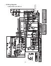
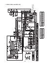
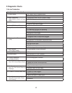
Legend: CB–control board; Comp–compressor; DV–drain valve; FMRs–fan
motors-remote; F/S–oat switch; HGVs–hot gas valves; HM–headmaster
(C.P.R.); LLVs–liquid line valves; PM–pump motor; TXVs–thermostatic
expansion valves; UF/S–upper oat switch; WV1–ll/rell water valve;
WV2–harvest water valve; X10–WV1 and WV2 control relay; X11–drain
valve/harvest pump timer relay; X12–drain valve lockout relay 1; X13–drain
valve lockout relay 2