


16
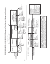
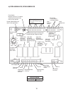
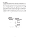
Dispensing Components
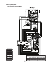
See "III.B. Wiring Diagrams"
for details.
Bin Control,
Control Switch,
Low Water Safety
Microprocessor (board revision level
indicated by last 2 digits on label)
"POWER" LED
(lights when
power is supplied
to the board)
"FLUSH" LED
(X6 Relay)
Drain Valve
"COMP" LED
(X2 Relay)
Compressor,
Fan Motor
10.5V
Transformer
High
Pressure
Switch
"GM" LED
(X1 Relay)
Gear Motor
"WTR" LED
(X5 Relay)
Dispensing
Water Valve
"ICE" LED
(X4 Relay)
Shutter Solenoid,
Dispensing Auger
Motor
24V In
24V Supply Out
115V In
Gear Motor
Protect Relay
Circuit
Portion Control
Timer
"AM" LED
(X3 Relay)
Agitating Motor
Drain Valve
24V Out
Dispensing Motor
115V Out
Dispensing
Water Valve
24V Out
24V In
Agitating Motor
115V Out
115V In
Gear Motor
115V Out
115V In
Counter Reset Button (not
used in this application)
Control Board
Part Number 2A2649-01
Flush Switch
Must be left in the "P" position,
otherwise the internal drain
timer will not operate.
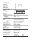
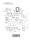
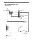
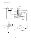
b) DCM-500BAH-OS, DCM-500BWH-OS