


3
IMPORTANT
This manual should be read carefully before the icemaker is serviced or
maintenance operations are performed. Only qualied service technicians
should install, service, and maintain the icemaker. Read the warnings
contained in this booklet carefully as they give important information regarding
safety. Please retain this booklet for any further reference that may be
necessary.
CONTENTS
I. Specications ...................................................................................................................... 5
A. Icemaker ....................................................................................................................... 5
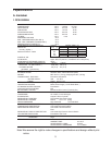
1. DCM-500BAH .......................................................................................................... 5
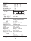
2. DCM-500BAH-OS ................................................................................................... 6
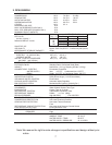
3. DCM-500BWH ......................................................................................................... 7
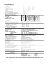
4. DCM-500BWH-OS .................................................................................................. 8
II. General Information ........................................................................................................... 9
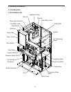
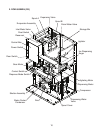
A. Construction .................................................................................................................. 9
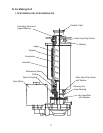
B. Ice Making Unit ............................................................................................................11
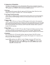
C. Sequence of Operation ............................................................................................... 12
1. Fill Cycle ................................................................................................................. 12
2. Ice Purge Cycle (60 seconds) ................................................................................ 12
3. Freeze Cycle .......................................................................................................... 12
4. Drain Cycle ............................................................................................................ 12
5. Shutdown ............................................................................................................... 12
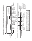
D. Control Board .............................................................................................................. 14
1. Control Board Layout ............................................................................................. 15
a) DCM-500BAH, DCM-500BWH ......................................................................... 15
b) DCM-500BAH-OS, DCM-500BWH-OS............................................................. 16
2. Features ................................................................................................................. 17
3. Controls and Adjustments ..................................................................................... 18
4. Control Board Check Procedure ............................................................................ 18
E. Float Switch ................................................................................................................. 20
III. Technical Information ...................................................................................................... 21
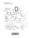
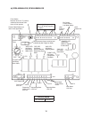
A. Water Circuit and Refrigeration Circuit ........................................................................ 21
B. Wiring Diagrams .......................................................................................................... 23
1. DCM-500BAH, DCM-500BWH .............................................................................. 23
2. DCM-500BAH-OS, DCM-500BWH-OS ................................................................ 24
C. Sequence of Electrical Circuit – Ice Making ................................................................ 25
1. Fill Cycle ................................................................................................................ 25
2. Ice Purge Cycle ..................................................................................................... 26
3. Freeze Cycle ......................................................................................................... 27
4. 12 Hour Drain Cycle / Drain Switch ....................................................................... 28
5. Shutdown ............................................................................................................... 29
6. Low Water Safety .................................................................................................. 30
7. High Pressure Switch ............................................................................................ 31
D. Sequence of Electrical Circuit – Dispensing .............................................................. 32
1. Continuous Dispense ............................................................................................. 32
2. Portion Dispense ................................................................................................... 33