


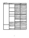
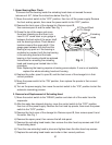

47
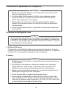
1) Always install a new drier every time the sealed refrigeration system is opened. Do not
replace the drier until after all other repair or replacement has been made. Install the
new drier with the arrow on the drier in the direction of the refrigerant ow.
2) Braze all ttings while purging with nitrogen gas owing at a pressure of 3 to 4 PSIG.
3) Use an electronic leak detector or soap bubbles to check for leaks. Add a trace of
refrigerant to the system (if using an electronic leak detector), and then raise the
pressure using nitrogen gas (140 PSIG). DO NOT use R-404A as a mixture with
pressurized air for leak testing.
3. Evacuation and Recharge (R-404A)
1) Attach a vacuum pump to the system. Be sure to connect the charging hoses to both
high and low-side access valves.
IMPORTANT
The vacuum level and vacuum pump may be the same as those for current
refrigerants. However, the rubber hose and gauge manifold to be used for
evacuation and refrigerant charge should be exclusively for POE oils.
2) Turn on the vacuum pump. Open the service manifold valves. Never allow the oil in the
vacuum pump to ow backwards.
3) Allow the vacuum pump to pull down to a 29.9" Hg vacuum. Evacuating period depends
on pump capacity.
4) Close the low-side valve and high-side valve on the service manifold.
5) Disconnect the vacuum pump and attach a refrigerant service cylinder to the high-side
line. Remember to loosen the connection and purge the air from the hose. See the
nameplate for the required refrigerant charge. Hoshizaki recommends only virgin
refrigerant or reclaimed refrigerant which meets ARI Standard No. 700-88 be used.
6) A liquid charge is recommended for charging an R-404A system. Invert the service
cylinder and place it on scales. Open the high-side valve on the service manifold.
7) Allow the system to charge with liquid until the proper charge weight is met.
8) If necessary, add any remaining charge to the system through the low-side. Use a
throttling valve or liquid dispensing device to add the remaining liquid charge through
the low-side access port with the unit running.
9) Close the service manifold valves and disconnect the service manifold hoses.
10) Cap the access valves to prevent a possible leak.