


IMPORTANT
This manual should be read carefully before the unit is serviced or maintenance
operations are performed. Only qualifi ed service technicians should install,
service, and maintain the unit. Read the warnings contained in this booklet
carefully as they give important information regarding safety. Please retain this
booklet for any further reference that may be necessary.
CONTENTS
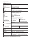
I. Specifi cations ------------------------------------------------------------------------------------------------ 1
A. Specifi cation Sheet ------------------------------------------------------------------------------------- 1
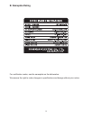
B. Nameplate Rating --------------------------------------------------------------------------------------- 2
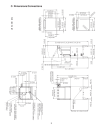
C. Dimensions/Connections ------------------------------------------------------------------------------ 3
II. General Information ---------------------------------------------------------------------------------------- 4
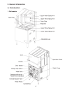
A. Construction ---------------------------------------------------------------------------------------------- 4
1. Dishwasher -------------------------------------------------------------------------------------------- 4
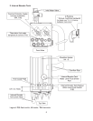
2. Internal Booster Tank ------------------------------------------------------------------------------- 5
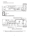
3. Control Box -------------------------------------------------------------------------------------------- 6
B. Sequence of Operation -------------------------------------------------------------------------------- 8
1. Auto Fill Cycle ----------------------------------------------------------------------------------------- 8
2. Ready Cycle (Unit Inactive) ----------------------------------------------------------------------- 9
3. Wash Cycle -------------------------------------------------------------------------------------------- 9
4. Rinse Cycle -------------------------------------------------------------------------------------------10
5. Drain----------------------------------------------------------------------------------------------------11
C. Sequence of Operation Flow Chart ----------------------------------------------------------------12
D. Control Board and Operation Board ---------------------------------------------------------------14
1. Control Board Location ----------------------------------------------------------------------------14
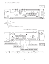
2. Control Board Layout ------------------------------------------------------------------------------15
3. Control Board Diagram ----------------------------------------------------------------------------16
4. Operation Panel Layout ---------------------------------------------------------------------------18
5. Features -----------------------------------------------------------------------------------------------18
6. Controls, Adjustments, and Lamps -------------------------------------------------------------18
7. Service Menu and Error Log ---------------------------------------------------------------------19
8. Temperature Display -------------------------------------------------------------------------------22
9. Error Codes ------------------------------------------------------------------------------------------23
10. Buzzer -------------------------------------------------------------------------------------------------23
11. Special Modes ---------------------------------------------------------------------------------------23
III. Service Diagnosis ----------------------------------------------------------------------------------------26
A. Diagnostic Procedure ---------------------------------------------------------------------------------26
B. Error Codes ----------------------------------------------------------------------------------------------28
1. Error Code Table ------------------------------------------------------------------------------------28
2. Error Code Log --------------------------------------------------------------------------------------29
3. Error Code Details ----------------------------------------------------------------------------------30
C. Service Flow Charts -----------------------------------------------------------------------------------39
1. Unit Will Not Start -----------------------------------------------------------------------------------39
2. Dishes Not Clean -----------------------------------------------------------------------------------41
i