


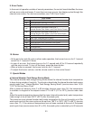
27
It is recommended to conduct this sequence check in the auto fi ll cycle after draining the
wash tank and internal booster tank. See “II.B. Sequence of Operation” for further details.
1) Move the power switch (GFCI) to the “OFF” position.
2) Pull out the overfl ow pipe to drain the wash tank.
3) Drain the internal booster tank through the drain hose.
4) Replace the overfl ow pipe and drain hose in their correct positions.
5) Enter the switch open/closed display mode according to the above procedure.
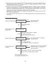
6) Auto Fill Cycle
a. When the door is closed and the door switch closes, segment B in the display comes
on, and the inlet water valve opens to start water supply.
b. After a while, the internal booster tank water level fl oat switch closes, segment C in
the display comes on, and the inlet water valve closes to stop water supply.
c. The rinse pump starts to feed water to the wash tank. When the internal booster tank
water level goes down, the water level fl oat switch opens, segment C in the display
goes off, and the inlet water valve opens to start water supply.
d. After the rinse pump is energized for a preset number of times to fi ll the wash tank,
the wash tank water level sensor closes, and segment D in the display comes on.
e. In normal operation, the internal booster tank backup water level fl oat switch does
not close, and segment A in the display stays off. If the internal booster tank water
level fl oat switch fails or the internal booster tank water level reaches the overfl ow
level, segment A comes on.
7) Wash Cycle
a. When the door is opened and closed again and the door switch closes, the wash
pump starts the wash cycle for a preset time. Segments B and D in the display stay
on.
b. If the internal booster tank is below the predetermined water level, segment C in the
display stays off. The inlet water valve stays open until segment C comes on.
c. When the wash cycle ends and the rinse cycle starts, the internal booster tank water
level goes down, and segment C in the display goes off. The inlet water valve stays
open until segment C comes on.
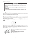
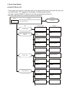
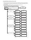
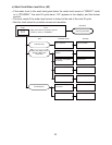
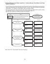
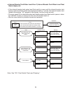
Diagnosis: If any problem is found by the above sequence check, refer to “III.B. Error
Codes,” “III.C. Service Flow Charts,” “D. Float Switch Check and Cleaning” and “E.
Thermistor Check.”