


47
D. Float Switch Check and Cleaning
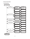
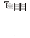
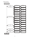
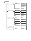
If an abnormal input signal is found by “III.A. Diagnostic Procedure” or the error code “o1”
or “o2” is displayed, check and clean/replace the fl oat switch according to the procedure
below.
1. Float Switch Check
To check the fl oat switch, follow the steps below.
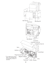
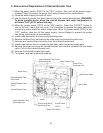
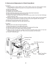
1) Remove the internal booster tank according to “IV.C. Removal and Replacement of Internal
Booster Tank.”
2) Remove the control box cover, and disconnect the CN8 connector from the control board
(see “II.D.2. Control Board Layout”).
3) To check the internal booster tank water level fl oat switch, check for continuity across the
red wires (#1 and #2) on the CN8 connector. Confi rm that the fl oat switch is open when
the fl oat is down and closed when the fl oat is up.
4) To check the internal booster tank backup water level fl oat switch, check for continuity
across the blue wires (#3 and #4) on the CN8 connector. Confi rm that the fl oat switch is
open when the fl oat is down and closed when the fl oat is up.
5) If any problem is found, repair or replace the fl oat switch.
6) If the fl oat switch is scaled up or dirty, clean it according to “2. Float Switch Cleaning.”
2. Float Switch Cleaning
Depending on local water conditions, scale may build up on the fl oat switch. Scale on the
switch can cause the fl oat to stick. In this case, the fl oat switch should be cleaned.
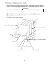
1) Remove the internal booster tank according to “IV.C. Removal and Replacement of Internal
Booster Tank.”
2) Use a soft brush to remove scale or soil on the fl oat swtich, or wipe down the fl oat switch
with a mixture of 1 part of recommended cleaner Hoshizaki “Scale Away” or “LIME-A-WAY”
(Economics Laboratory, Inc.) and 25 parts of warm water.
3) Rinse the parts thoroughly with clean water.
4) If the fl oat switch is removed, replace it in its correct position. Be careful not to confuse
the positions and directions of the internal booster tank water level fl oat switch and the
internal booster tank backup water level fl oat switch. Make sure the fl oats can move freely
in the vertical directions (see “II.A.2. Internal Booster Tank”).
5) Replace the internal booster tank in the reverse order of the removal procedure (see “IV.
C. Removal and Replacement of Internal Booster Tank”).