


23
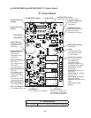
b) KM-1601SWH/3 and KM-1601SRH/3 "E" Control Board
IMPORTANT
KM-1601SWH/3 and KM-1601SRH/3 utilize an "E" control board and TBC.
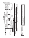
The steps in the sequence are as outlined below. When power is supplied, CB red
"POWER OK" LED turns on. There is a 5-second delay before startup. Note that the
order of the component LEDs from the outer edge of CB is 1, 4, 3, 2.
(1) 1-Minute Fill Cycle
LED 4 is on. WV energizes and the 1-minute ll cycle begins. After 1 minute, CB
checks for a closed F/S. If F/S is closed, the harvest cycle begins. If open, WV remains
energized through additional 1-minute ll cycles until water lls the water tank and closes
F/S. This serves as a low water safety to protect PM.
(2) Initial Harvest Cycle
LEDs 1, 4, and 2 are on. WV remains energized, Comp, FMR, HGV energize. CB
monitors the warming of the evaporator via the thermistor located on the suction line.
When the thermistor reaches 48°F (9°C), CB reads a 3.9 kΩ signal from the thermistor
and turns harvest termination over to the harvest timer (S4 dip switch 1 & 2). The harvest
timer has settings of 60, 90, 120, and 180 seconds. For details, see "II.C.3.b) Harvest
Timer (S4 dip switch 1 & 2)." WV is energized during harvest for a maximum of 6 minutes
or the length of harvest, whichever is shorter. LED 4 turns off when WV de-energizes.
When the harvest timer terminates, the harvest cycle is complete. CB checks the position
of F/S and proceeds to the next cycle if it is closed or calls for a 1-minute ll cycle if it is
open. The minimum total time allowed by CB for a complete harvest cycle is 2 minutes.
(3) Freeze Cycle
LED 1 is on. Comp and FMR remain energized, PM and LLV energize, HGV and WV
de-energize. The unit is held in freeze by a 5-minute short cycle protection timer (CB will
not accept a signal from F/S during the rst 5 minutes of freeze). After the 5-minute short
cycle protection timer terminates, CB turns freeze termination over to F/S. As ice builds
on the evaporator, the water level in the water tank lowers. The freeze cycle continues
until F/S opens and terminates the cycle.
(4) Pump-Out Cycle
LEDs 1, 3, and 2 are on. LED 4 is on when S4 dip switch 3 & 4 are set to 3 off and
4on. For details, see "II.C.3.c) Pump-Out Timer (S4 dip switch 3 & 4)." Comp and FMR
remain energized. HGV energizes. WV energizes if S4 dip switch 3 off and 4 on. LLV
de-energizes. PM stops for 2 seconds then reverses, taking water from the bottom of the
water tank and forcing pressure against the pump-out check valve seat allowing water to
go through the pump-out check valve and down the drain. At the same time, water ows
through the small tube to power ush F/S. When the pump-out timer terminates, the
pump-out is complete.
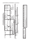
The rst pump-out occurs after the 1st freeze cycle, then every 10th cycle thereafter. The
pump-out frequency is factory set, and generally no adjustment is required. However,
where water quality is bad and the icemaker needs a pump-out more often, the pump-out
frequency can be adjusted. The pump-out frequency control (S4 dip switch 5 & 6) can
be set to have a pump-out occur every cycle, or every 2, 5, or 10 cycles. For details, see
"II.C.3.d) Pump-Out Frequency Control (S4 dip switch 5 & 6)."