


26
F/S check
1 to 3-min. timer in control
(S4 dip switch 1 & 2)
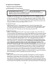
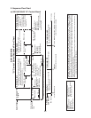
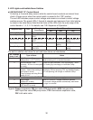
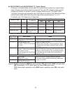
"E" Control Board Sequence Flow Chart
1. 1-Minute Fill
Cycle
Cycle Steps
2. Harvest Cycle
•WVtime:6min.orthelengthofharvest,whichever
is shorter.
•Maximumharvesttime:20min.
Thermistor
in control
3. Freeze Cycle
•Minimumfreezetime:5min.
•Maximumfreezetime:freezetimersetting
(S4 dip switch 9 & 10)
F/S in control
4. Pump-Out Cycle
•Factorysetforevery
10th cycle (S4 dip
switch 5 & 6)
•Pumpmotorstopsfor
2 sec., then reverses
for 10/20 sec. (S4 dip
switch 3 & 4)
WV energized
F/S open
WV continues
Comp energized
FMR energized
HGV energized
Thermistor temperature
reaches 48°F (9°C)
(3.9 kΩ or less).
Harvest timer starts.
F/S open
Comp continues
FMR continues
PM energized
LLV energized
HGV de-energized
WV de-energized
F/S closed
Comp continues
FMR continues
HGV energized
PM de-energizes for 2 sec.,
then reverses for 10/20 sec.
LLV de-energized
F/S check
Startup begins
here after 5-sec.
delay
If F/S is open, compressor stops and cycle returns to 1-Minute Fill Cycle
5-min. timer in
control
F/S closed
F/S open or freeze
timer terminates
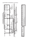
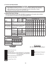
KM-1601SWH/3 and KM-1601SRH/3
1. Bin Full
Within 10 sec. after ice contacts TBC
bulb, unit shuts down.
TBC Operation
Ice contacts TBC bulb
2. Icemaker Off
All components de-energized.
3. Ice Level Lowered
No ice touching TBC bulb. Icemaker
starts at "1. 1-Minute Fill Cycle."
TBC closedTBC-open
All components de-energized
To 1 above
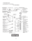
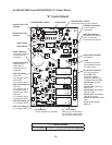
b) KM-1601SWH/3 and KM-1601SRH/3 "E" Control Board
Legend:
Comp–compressor
FMR–fan motor-remote
F/S–oat switch
HGV–hot gas valve
LLV–liquid line valve
PM–pump motor
TBC–thermostatic bin control
WV–inlet water valve
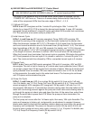
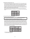
Components Energized when the Control Switch is in the "WASH" Position
The "WASH" position on the control switch is used when cleaning and sanitizing the unit. When in the "WASH" position,
power is supplied to the pump motor. With the cleaning valve closed, the cleaner and sanitizer ow over the outside of
the evaporator plate assembly. With the cleaning valve open, the cleaner and sanitizer ow over both the outside and the
inside of the evaporator plate assembly.
Note: Close the cleaning valve after cleaning and sanitizing are complete, otherwise the unit will not restart when the
control switch is placed in the "ICE" position.
Shutdown
and Restart