


mi?RY3iBEABEQUATEGMSU9PLY
~ ‘four range is designed to operate at a pressure
~’()[4 inches of water column on natural gas or, if
.Z:Itsigned for LP gas (propane or butane), 10
~lnchesoof water column. Nflakesure you are
‘)supplyln~ your range with the type of gas for
~~~hichit is designed. If, at any time in the future,
you decide to use this range on a different
type
of
gas, conversion adjustments must be made
I)ya service technician or other qualtied
person before attempting to operate the range
on that gas.
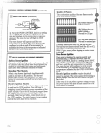
I~orproper operation, the pressure of natural gas
supplied to the regulator must be between 4 and
13inches ofwater column. For LP gas, the
pressure supplied must be between 10 and 13
inches of water column. When checking for
proper operation of the regulator, the inlet
pressure must beat least 1 inch greater than the
operating (manifold) pressure as given above. me
pressure regulator located at the inlet of the range
manifold must remain in the supply line
regardless of whether natural or LP gas is being
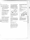
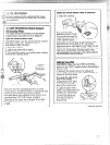
used. A flexibie metal appliance connector used to
connect the range to the gas supply line should
have an I.D. of 1/21’and be 5 feet in length
(shorter and longer lengths are acceptable) for
ease of installation.
. ..—.
.-..... ——---
—.—
Shut
off the main gas supplyvalvebefore
~isconnecting the oldrange and leave it off until
Iew hook-up has been completed. Don’t forget to
-e]ight the pilot on other gas appliances when you
turn the gas back o~I.
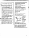
l~ecausehard piping restricts movement ofthe
range, the use Gfan A.G.A.-certtied flexiblemetal
applianceconnector is recommended unless local
codes require a hard-piped connection. Never use
an old connector when installinga new range. If
{hi’har{lpipinglllethod is used, you must
careiuliy aii<qnthe pipe;the
range cartnotbe
~~](lveclZLftei-the connection is macle.
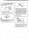
‘~’c~
~>~~v~nt gas leaks, pu~pipe joint compound 011,
01.wrap l]ipi~thread tape wit-h‘~eflon*
around, all
ll~[de(ex(ernal) pipe threads.
‘!’,I1{JI1:]<~~~is({~]-~{]li-:~c~ci~larl(
~iI)tiI’{111[
..——
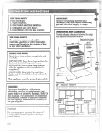
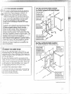
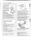
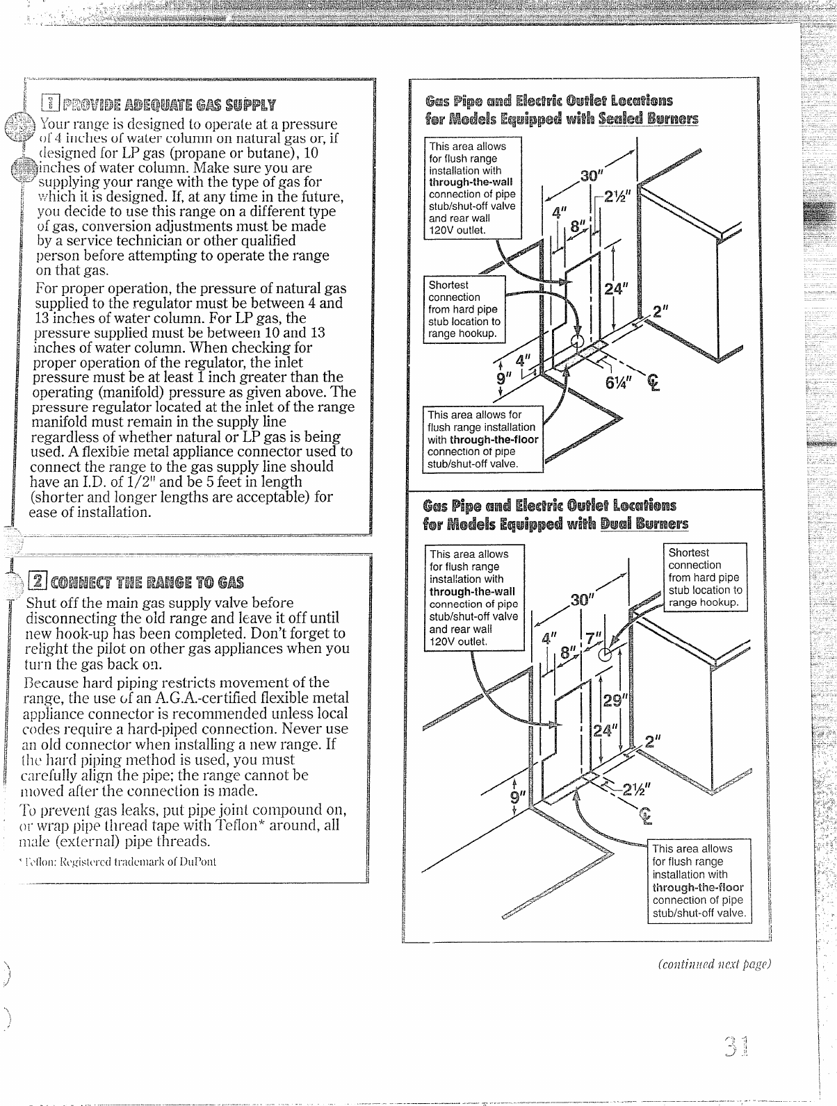
mare. allows-l
.
forflush range
itlstallation wi!h
through-the-wall
connectionof pipe
stub!shut-offvalve
and rearwall
120Voutlet.
/
2“
\
>
%
/
1
24”
I
/
./
This area allows
I
Shortest
1
A
for flush range
instal~ationwith
through-the-wall
connection of pipe
stub/shut-off valve
and rearwall
120Voutlet.
/
#
y“
/“’”
I
- —