


Rev. 0010
5
FINISHING TOUCHES
(PERFORM AFTER PLUMBING AND ELECTRICAL)
ACCESS PANELS
All electrical and drain access panels are clearly labeled
on the deck of the stand. .
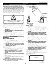
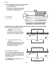
INSTALLING SPLASHGUARD
After merchandisers have been leveled and joined and all
electrical and plumbing work has been completed, install
the splashguards. After adjusting brackets flush with the
floor, position splashguard up behind the front panel
first—then position the lower portion over the previously
adjusted brackets. Splashguards may be sealed to the floor
using a vinyl cove base trim. The size of trim needed will
depend on how much the floor is out of level.
NOTE: The splashguard must be removable to access compo-
nents behind it.
1. Remove all dirt and wax (etc.) from the area of the
splashguard to ensure a secure adhesion.
2. Apply a good contact cement to the trim, allowing
for proper dry-time.
3. Install trim to the splashguard so that it is flush with
floor.
Do not seal trim to floor!
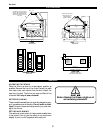
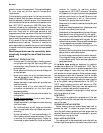
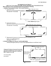
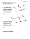
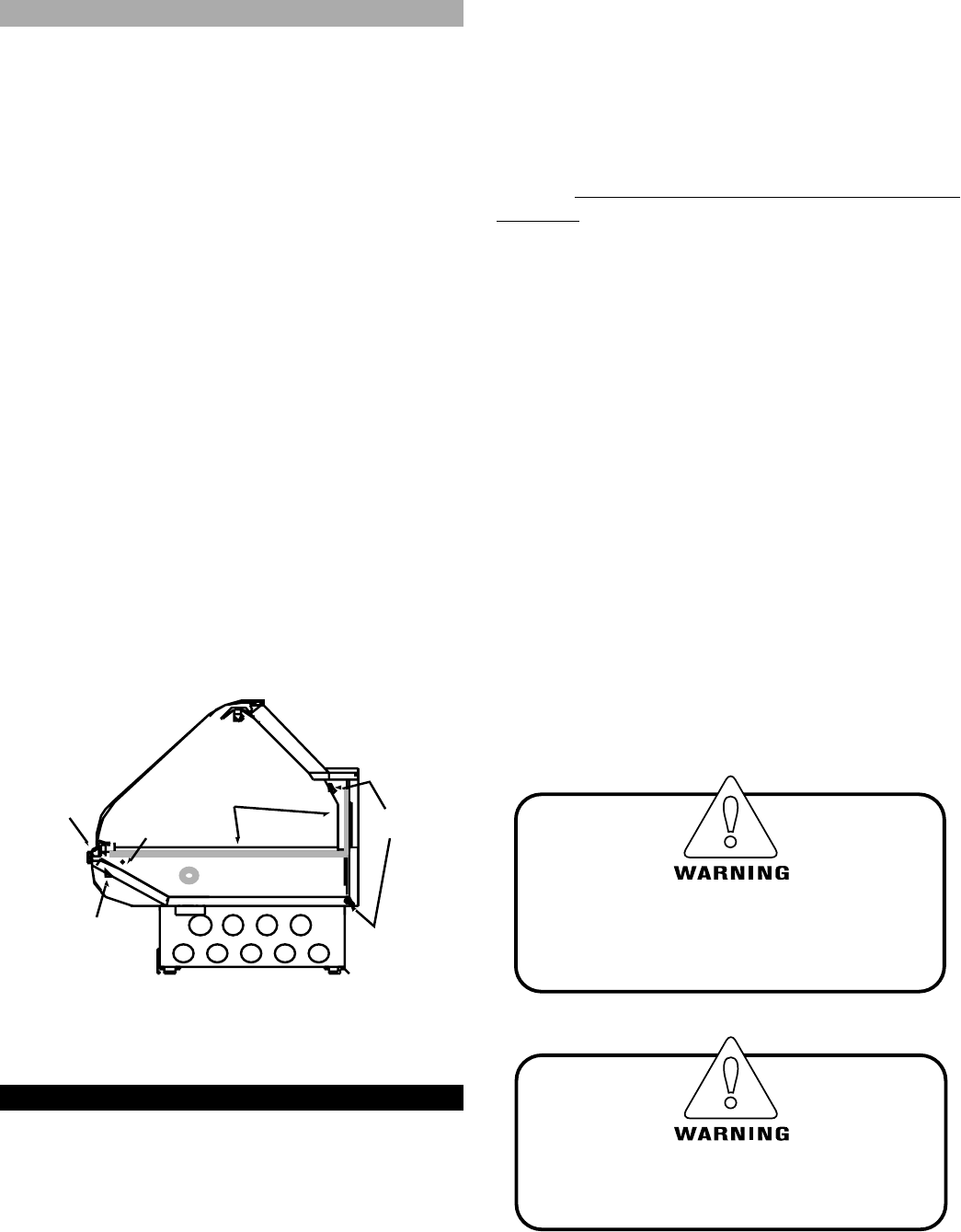
BOLT AND SEALANT LOCATIONS
CAMLOCK
&
SEALANT
LOC ATI O NS
CAMLOCK
LOCATION
(BOLT BRACKET
IN WEDGES)
APPLY SEALANT
TO SHADED AREA
JOINT BACKER
LOCATION CAMLOCK
LOCATIONS
SEALAROUND PIPING
ACCESS HOLES
BOLT INSIDE
WEDGES
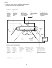
Plumbing
WASTE OUTLET
The waste outlet is located under the hot wells and can
be accessed from the back.
Drain is 1" copper. A stub is provided for extending to
sink. Drain must be run in a material that will withstand a
150°F (66°C) (or more) temperature, such as copper.
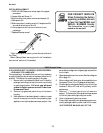
WATER SUPPLY CONNECTION
The well fill water hose on these models will need to be
connected to a water supply. The water connection is 1/
2", and consists of a hand gate valve. If the water pressure
exceeds 45 psi, a water pressure regulating valve should
be installed in the supply line, and set at 30-35 psi outlet
pressure. The pressure regulating valve is not supplied by
Hussmann.
For a quick preheat time, the customer may want to
pipe in hot water. If hot water is piped into the case, tem-
perature of water supply must not exceed 150°F(66°C).
In areas where water contains a heavy mineral content, it
may be a good idea to install a cartridge-type water filtra-
tion system.
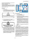
Proper water depth is 1". These cases come equipped
with an auto-fill system designed to slowly feed in water
to maintain the proper water level, and prevent damage
incurred when cold water is fed too fast into a hot well.
In common well configurations, the water level is regu-
lated by adjusting the probe on the inside of the well. In
multi-well configurations, use the sliding plate at the rear
of the case to adjust the float level. The water level is main-
tained in direct relation to the vertical position of the
plate. The water feeds in slowly, so it is not necessary to
shut water off during cleaning. It is advisable to allow a
number of hours for the system to refill. If necessary, the
case may also be filled manually, with the use of buckets.
NOTE: Some local codes may require the installation of check
valves in the water supply.
Do not plumb below the sliding plate
on the side of the hot well!
Doing so may interfere with the
ability to adjust the water within the well!
Damage may occur if cold water is fed
into a preheated hot well too quickly!
Installation cont.