


Rev. 0108
7
Refrigeration
REFRIGERANT TYPE
The standard refrigerant will be R-22 unless otherwise
specified on the customer order. Check the serial plate
on the case for information.
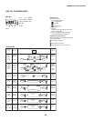
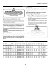
REFRIGERATION LINES
LIQUID SUCTION
3/8" O.D. 5/8" O.D.
NOTE: The standard coil is piped at 5/8" (suction); however,
the store tie-in may vary depending on the number of
coils and the draw the case has. Depending on the case
setup, the connecting point in the store may be
5
/8",
7
/8", or 1
1
/8". Refer to the particular case you are
hooking up.
Refrigerant lines should be sized as shown on the refrig-
eration legend furnished by the store.
Install
P-traps (oil traps) at the base of all suction line ver-
tical risers.
Pressure drop can rob the system of capacity. To keep the
pressure drop to a minimum, keep refrigerant line run as
short as possible, using the minimum number of elbows.
Where elbows are required, use long radius elbows only.
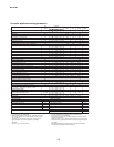
CONTROL SETTINGS
See the “Case Specs” section of this guidebook for the
appropriate settings for your merchandiser. Maintain these
parameters to achieve near constant product tempera-
tures. For all multiplexing, defrost should be time termi-
nated. Defrost times should as directed in the Case Speci-
fications section of this guide. The number of defrosts per
day should never change. The duration of the defrost cycle
may be adjusted to meet conditions present at your loca-
tion.
0°F / -18°C or less air temperature. Adequate performance
is assured by the desired condition of the product in case.
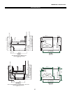
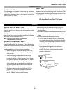
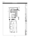
ACCESS TO TX VALVES & DRAIN LINES
MECHANICAL - Remove product from end of case. Remove
product racks. Remove refrigeration and drain access panels
(labeled). TX valve (mechanical only) and drain are located
under each access panel at end of the case.
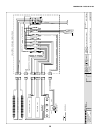
ELECTRONIC - The Electronic Expansion valve master and
slave cylinder(s) are located within the electrical access
panel(s).
ELECTRONIC EXPANSION VALVE (OPTIONAL)
A wide variety of electronic expansion valves and case
controllers can be utilized. Please refer to EEV and con-
troller manufacturers information sheet. Sensors for elec-
tronic expansion valves will be installed on the coil inlet,
coil outlet, and in the discharge air. (Some supermarkets
require a 4th sensor in the return air). Case controllers
will be located in the electrical raceway or under the case
THERMOSTATIC EXPANSION VALVE LOCATION
This device is located on the same side as the refrigera-
tion stub. A Sporlan balanced port expansion valve model
is furnished as standard equipment, unless otherwise speci-
fied by customer.
EXPANSION VALVE ADJUSTMENT
Expansion valves must be adjusted to fully feed the evapo-
rator. Before attempting any adjustments, make sure the
evaporator is either clear or very lightly covered with frost,
and that the fixture is within 10°F of its expected operat-
ing temperature.
MEASURING THE OPERATING SUPERHEAT
1. Determine the suction pressure with an accurate
pressure gauge at the evaporator outlet.
2. From a refrigerant pressure temperature chart,
determine the saturation temperature at the
observed suction pressure.
3. Measure the temperature of the suction gas at the
thermostatic remote bulb location.
4. Subtract the saturation temperature obtained in step
No. 2 from the temperature measured in step No. 3.
3. The difference is superheat.
5. Set the superheat for 5°F - 7°F.
Multiplexing - Piping of merchandisers operating on the
same refrigeration system may be run from merchandiser
to merchandiser through the end frame saddles provided
for this purpose. DO NOT RUN REFRIGERANT
LINES THROUGH MERCHANDISERS THAT ARE
NOT THE SAME REFRIGERATION SYSTEM as this
may result in poor refrigeration control and compressor
failure.
Line Sizing - Refrigerant lines should be sized as shown
on the refrigeration legend that is furnished for the store
(not furnished by Hussmann). If a legend has not been
furnished, refer to the Hussmann Application Engineering
Manual for guidance.
Oil Traps - P-traps (oil traps) must be installed at the
base of all suction line vertical risers.
Pressure Drop - Pressure drop can rob the system of
capacity. To keep the pressure drop to a minimum, keep
the refrigerant line run as short as possible using a minimum
number of elbows. Where elbows are required, use long
radius elbows only.
Insulation - The suction and liquid lines should be clamped
or taped together and insulated for a minimum of 30’ from
the merchandiser. Additional insulation is recommended
wherever condensation drippage is objectionable.