


Rev. 0108
9
Electrical
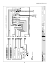
WIRING COLOR CODE
GREEN GROUND
PURPLE ANTI-SWEAT
ORANGE LIGHTS
YELLOW RECEPTACLE
RED / BLACK T-STAT /SOLENOID230V
BLACK / WHITE T-STAT / SOLENOID 115V
BROWN FAN MOTORS
CASE MUST BE GROUNDED
NOTE: Refer to label affixed to case to determine the actual
configuration as checked in the “TYPE INSTALLED” boxes.
ELECTRICAL CIRCUIT IDENTIFICATION
Standard lighting for all models will be full length fluores-
cent lamps located within the case at the top.
The switch controlling the lights, the plug provided for
digital scale, and the thermometer are located at the rear
of the case mullion.
ELECTRICAL SERVICE RECEPTACLES
(WHEN APPLICABLE)
The receptacle that is provided on the exterior back of
these models is intended for computerized scales with a
fifteen amp maximum load, not for large motors or other
high wattage appliances. It should be wired to a dedicated
circuit.
BEFORE SERVICING
ALWAYS DISCONNECT ELECTRICAL
POWER AT THE MAIN DISCONNECT
WHEN SERVICING OR REPLACING ANY
ELECTRICAL COMPONENT.
This includes (but not limited to) Fans, Heat-
ers, Thermostats, and Lights.
FIELD WIRING & SERIAL PLATE AMPERAGE
Field Wiring must be sized for component amperes
printed on the serial plate. Actual ampere draw may be
less than specified. Field wiring from the refrigeration
control panel to the merchandisers is required for re-
frigeration thermostats. Most component amperes are
listed in the “Case Specs” section, but always check the
serial plate.
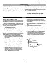
BALLAST LOCATION
Ballasts are located within the access panel that runs
the length of the rear of the case.
WIRING & SERIAL PLATE AMPERAGE
Field Wiring must be sized for component amperes
stamped on the serial plate. Actual ampere draw may be
less than specified. Field wiring from the refrigeration con
trol panel to the merchandisers is required for refrigera-
tion thermostats. Most component amperes are listed in
the "Case Specs" section, but always check the serial plate.
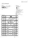
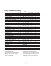
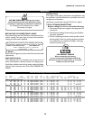
ASHRAE COLOR CODE
NOTE: All other manufacturers; no known sensor codes
Case Control Systems
SENSOR COLORS
Manufacturer ® > EIL CPC
Location
Coil Inlet
Color
Blue Blue
Part#
225-01-1755225-01-325
5
Coil Outlet
Color
Red Red
Part#
225-01-1757225-01-312
3
Discharge Air
Color
Green Green
Part#
225-01-1756225-01-326
0
Return Air
Color
Purple Green
Part#
225-01-1758225-01-326
0
Defrost Term.
Color
White Orange
Part#
225-01-0650225-01-325
4
Liquid Line
Color
White Blue
Part#
225-01-0650225-01-325
5
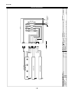
REAR CLOSE-OFF PANEL
To perform electrical and refrigeration work, remove the
rear closure panel by loosening the sheet metal screws.
Replace when work is complete.
ELECTRICAL
Connections - All wiring must be in compliance with
NEC and local codes. All electrical connections for the
nonrefrigerated model are to be made in the electrical
panel. Electrical connections for refrigerated models are
made in the electrical box on the back of the case behind
the rear close-off panel.
Field Wiring - Field wiring must be sized for components
amperes stamped on the serial plate. Actual ampere draw
may be less than specified. Always check the serial plate.
Post Construction Clean-up - After the first two weeks
of a major store remodel or new store operation, the grill
should be removed and the condensing unit and condenser
face cleaned due to the accumulated dirt and debris
generated during construction.