


Buccaneer GT, Falcon GTE - Installation, Assembly & Servicing
17
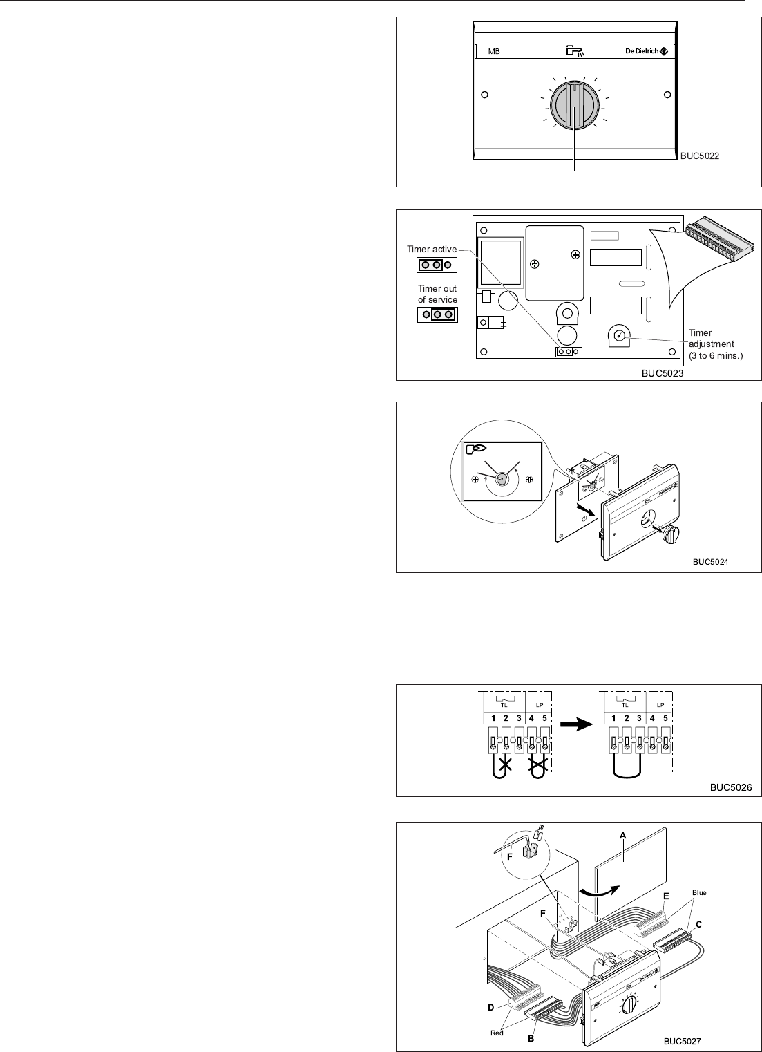
ASSEMBLY
1. Instructions for use
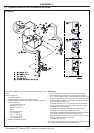
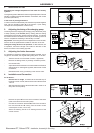
Regulating the storage temperature of hot water for sanitary
systems:
The regulating button A allows for the average temperature of stored
sanitary hot water to be adjusted between 10 and 80ºC, with a hard
point at 6 (about 60ºC).
In the event of prolonged absence:
In order to ensure that the sanitary hot water tank is protected against
frost, set the regulating button A to the position 1 (this setting
corresponds to a temperature of about 10ºC).
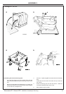
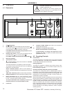
2. Adjusting the timing of the charging pump
The timing device for stopping the charging pump allows the pump
to keep operating for 4 minutes (factory setting) after the setting
temperature for the sanitary system has been reached. This allows
the residual heat accumulated in the body of the heating unit to be
used to complete the reheating of the sanitary hot water.
Adjustment: This timing device can be adjusted from 3 to 6 minutes,
with the aid of the potentiometer located on the back of the unit.
Taking the timing device out of operation: To take the timer out
of operation, remove the bridge unit located on the back of the
device, as shown in the drawing opposite.
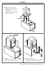
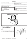
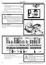
3. Adjusting the limiter thermostat
It is possible to change the setting of the limiter thermostat, over a
range from 30 to 90ºC, the original setting being 80ºC. To do this:
- Take the module out of the boiler console, if applicable;
- Remove the setting button, by drawing it towards yourself;
- Unhook the PCB;
- Adjust the limiter thermostat in accordance with the reference
settings shown in the diagram opposite, with the aid of a flat
screwdriver;
- Reassemble the unit by proceeding in the reverse order.
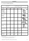
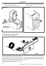
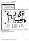
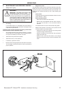
4. Installation and Connection
For all boilers:
- Remove the TL bridge, connected to the terminal strip of
the boiler control console, with terminals 1 and 2 to terminals
1 and 3.
- Withdraw the LP bridge at terminals 4 and 5 in order to do
away with an ECS priority.
Main
Terminal
Strip
6
5
4
3
2
8
7
1
A
T
MINI MAXI
T=0
TEMPO
80 C
90 C
30 C
1
2
3
4
5
6
7
8
MB
80ºC
90ºC 30ºC
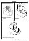
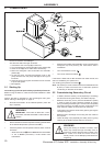
- Remove the panel A from the control console of the boiler
(refer to the technical instruction plate).
- Connect the connector elements B and C of the module to
the connectors D and E coming from the boiler control
console (blue on blue, red on red).
- Attach the earthing wire F to an earthing terminal of the
control console.