


18
Buccaneer GT, Falcon GTE - Installation, Assembly & Servicing
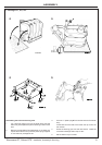
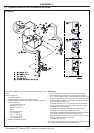
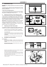
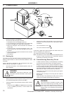
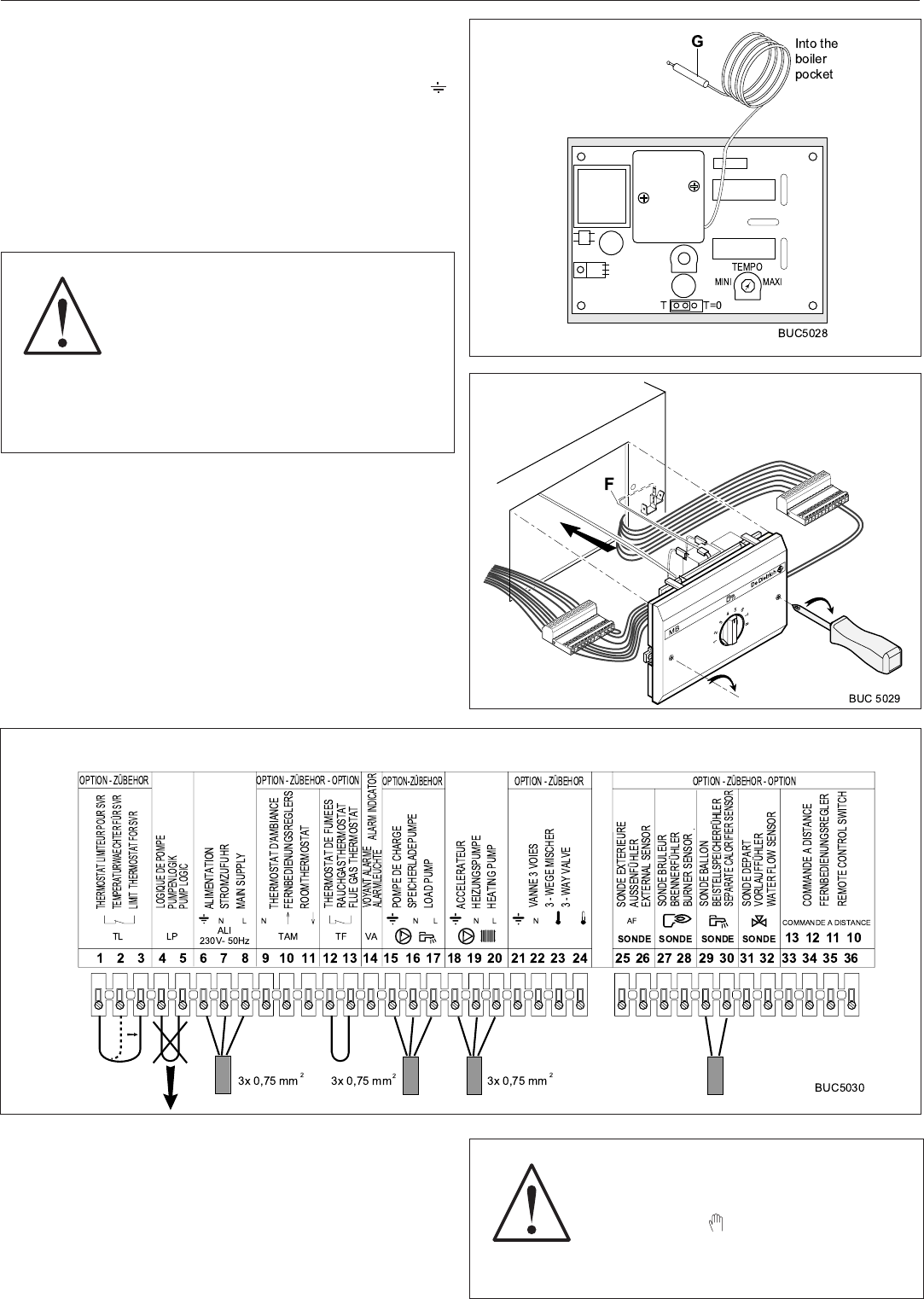
- Introduce the bulb G of the limiter thermostat into the boiler
pocket.
- Connect the charging pump to the boiler control console,
ensuring that the terminals live (L), neutral (N) and earth ( )
are properly attached.
- Connect the probe bulb to the boiler control console.
- Introduce the probe bulb into the pocket of the sanitary hot
water tank.
If the tank is already fitted with a thermostat, it will not be used :
accordingly replace the bulb of this thermostat with the tank probe.
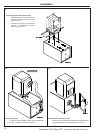
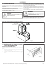
Securing the module
Mount the module by the front so as to secure it with the help of the
two screws located on the front section (use a cruciform (Phillips)
screwdriver).
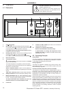
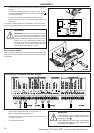
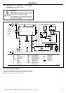
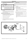
Connections (Installation with MB1 Module)
- Move bridge TL from terminals 1-2 to terminals 1-3.
- Remove bridge LP from terminals 4-5.
- Connect the power supply, the heating pump and the tank
load pump as shown.
- Connect the tank sensor.
WARNING
IMPORTANT: Under no circumstances may the
wires of the probe (very low voltage) and wires
carrying 230 V supply feed be placed in the same
conduit or cable duct. Make sure that a minimum
interval of 10 cm is maintained between them.
Failure to do so can cause interference and lead
to malfunction of the control system and the
deterioration of the electronic circuits.
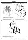
ASSEMBLY
WARNING
If the installation includes an MB1 module and no
room thermostat (TAM), set three position switch
5 (see page 14) to .
If the installation includes an MB1 module and a
room thermostat (TAM), set three position switch
5 (see page 14) to AUTO.