


Buccaneer GT, Falcon GTE - Installation, Assembly & Servicing
19
ASSEMBLY
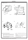
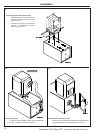
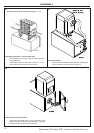
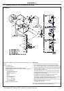
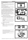
4.6 Heating and Domestic Hot Water
Installation (with MB1 module)
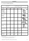
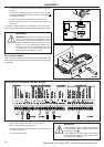
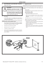
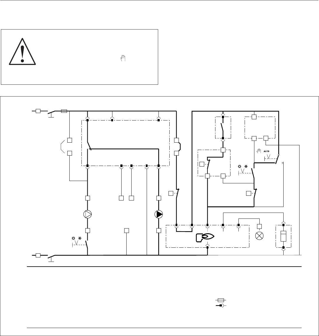
4.7 Connecting the Burner
The boiler is fitted with a cable with a 7-pin European connecting
plug which can be plugged into the socket supplied with the burners
(see the instructions supplied with the burner).
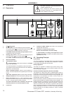
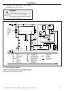
F 6,3AT
Remove
bridge LP
to benefit
from the
heating
pump
logic
ZG
ZG
L
N
LP TF*
TS
(RG)*
(RG)*
(TL)*
ZEH 1
TCH
(TAM)*
A
ZEH 2
P*
ZT
(B)
(CH)*
BA
BA
BA
BA
8
BA
7
23
24 19 20 16
25
21
22
18
26
4
5
20
BA BA
24
BA
13
BA
12
BA
1723
BA
19
BA
22
BA
16
L1 T1 T2 B4 S3
BA
14
1
23
11
10 9
h
N
qq
q
BUC5031
A
B
BA
CH
CS
F6, 3AT
L
LP
N
P
Heating pump
Burner
Connection strip
Time counter
Safety contact
Fuse
Phase
Pump logic
Neutral
Filling pump
RG
TAM
TCH
TF
TL
TS
VA
V3V
ZEH1
Control unit
Room thermostat
Boiler thermostat
Flue gas thermostat
Limiting thermostat
Safety thermostat
Alarm indicator
Three-way valve
Burner Summer/
Winter switch
ZEH2
ZG
ZT
*
Heating pump Summer/
Winter switch
Main switch
Test switch
Optional
Connecting strip
Connector
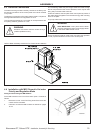
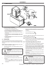
TEST
STB
WARNING
IMPORTANT: If the installation includes an MB1
module and no room thermostat (TAM), set three
position switch 5 (see page 14) to .
If the installation includes an MB1 module and a
room thermostat (TAM), set three position switch
5 (see page 14) to AUTO.