


JFT Series Technical Manual 7610-002-77-38
Issued: 03-16-2006 Revised: N/A
14
SECTION 2: INSTALLATION/OPERATION INSTRUCTIONS
INSTALLING THE JFT DISHMACHINE (CONTINUED)
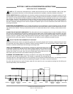
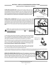
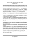
CONNECTING THE DRAIN LINE: The drains for the models covered in this manu-
al are gravity discharge drains. All piping from the 2” connection on the load section
must be pitched (1/4” per foot) to the floor or sink drain. All piping from the machine
to the drain must be a minimum 3” N.P.T. and shall not be reduced. There must also
be an air gap between the machine drain line and the floor sink or drain. If a grease
trap is required by code, it should have a flow capacity of 30 gallons per minute.
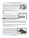
WATER SUPPLY CONNECTION: Ensure that you have read the section entitled
“PLUMBING THE DISHMACHINE” above before proceeding. Install the water supply
line (3/4” pipe size minimum) to the dishmachine line strainer using copper pipe. It is rec-
ommended that a water shut-off valve be installed in the water line between the main
supply and the machine to allow access for service.The water supply line is to be capa-
ble of 20±5 PSI “flow” pressure at the recommended temperature indicated on the data
plate.
NOTE: Units equipped with electric final rinse boosters should have the power
switch for the booster inspected to ensure it is in the ON
position. The booster will
not work unless this is so.
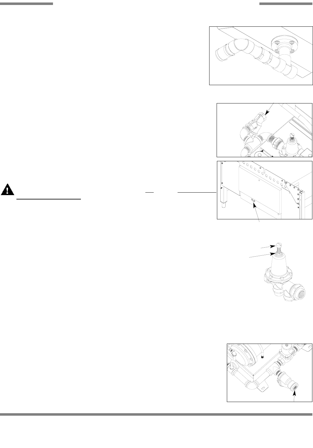
In areas where the water pressure fluctuates or is greater than the recommended pres-
sure, it is suggested that a water pressure regulator be installed. The models covered
in this manual do come with water pressure regulators as standard equipment. Please
notify Jackson immediately if this component is not present on your machine.
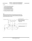
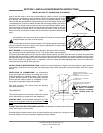
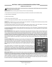
If the water level is too low or too high, check the incoming water pressure. It should
be 20 ± 5 PSI. Too high of pressure results in too much water; too low of pressure
results in too little water. To adust the regulator, loosen the nut at the top, this will allow
you to screw or unscrew the adjustment. With a screwdriver, turn the adjuster clock-
wise to increase pressure or counter clockwise to decrease it.
Do not confuse static pressure with flow pressure. Static pressure is the line pressure
in a “no flow” condition (all valves and services are closed). Flow pressure is the pres-
sure in the fill line when the fill valve is opened during the cycle.
It is also recommended that a shock absorber (not supplied) be installed in the incoming water line. This prevents line hammer
(hydraulic shock), induced by the solenoid valve as it operates, from causing damage to the equipment.
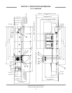
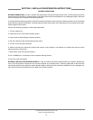
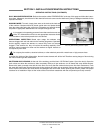
STEAM LINE CONNECTIONS (JFT-S ONLY): The JFT-S is designed to use low pressure
steam as a source of heat for the water. The machines come with lines by which the source
steam needs to be connected. The inlet steam is connected to the machine via a 1” FNPT
Y-Strainer located underneath the Electrical Section. The 1” steam supply line is to be capa-
ble of 20±5 PSI. Connect all steam lines to the machine as all applicable codes provide.
See machine data plate for information concerning steam flow pressure.
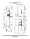
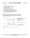
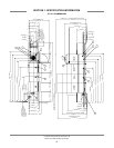
Load End Drain Connection
3/4” Water Supply Connection
Final Rinse Booster Power Switch
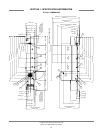
Adjusting screw
Locking nut
Water Pressure Regulator
Steam Line Connection Y-strainer